Magnetic recording medium and magnetic recording apparatus

Inactive Publication Date: 2012-08-23
HITACHI LTD
View PDF6 Cites 18 Cited by
  • Summary
  • Abstract
  • Description
  • Claims
  • Application Information

AI Technical Summary

Benefits of technology

[0025]The magnetic recording medium according to the present invention is a high density magnetic recording medium including a magnetic rec

Problems solved by technology

Particularly, when a nonconductor film is formed, the deposition rate of the RF sputtering method is remarkably low.
Accordingly, if the deposition rate of a part of the layers is low, the deposition time thereof becomes a bottleneck, which reduces manufacturing throughput.
Accordingly, when a nonconductor such as MgO is formed by an RF sputtering method, a thick layer thereof cannot be deposited by the mass production process

Method used


Image

  • Magnetic recording medium and magnetic recording apparatus
  • Magnetic recording medium and magnetic recording apparatus
  • Magnetic recording medium and magnetic recording apparatus

Examples


Example

First Example

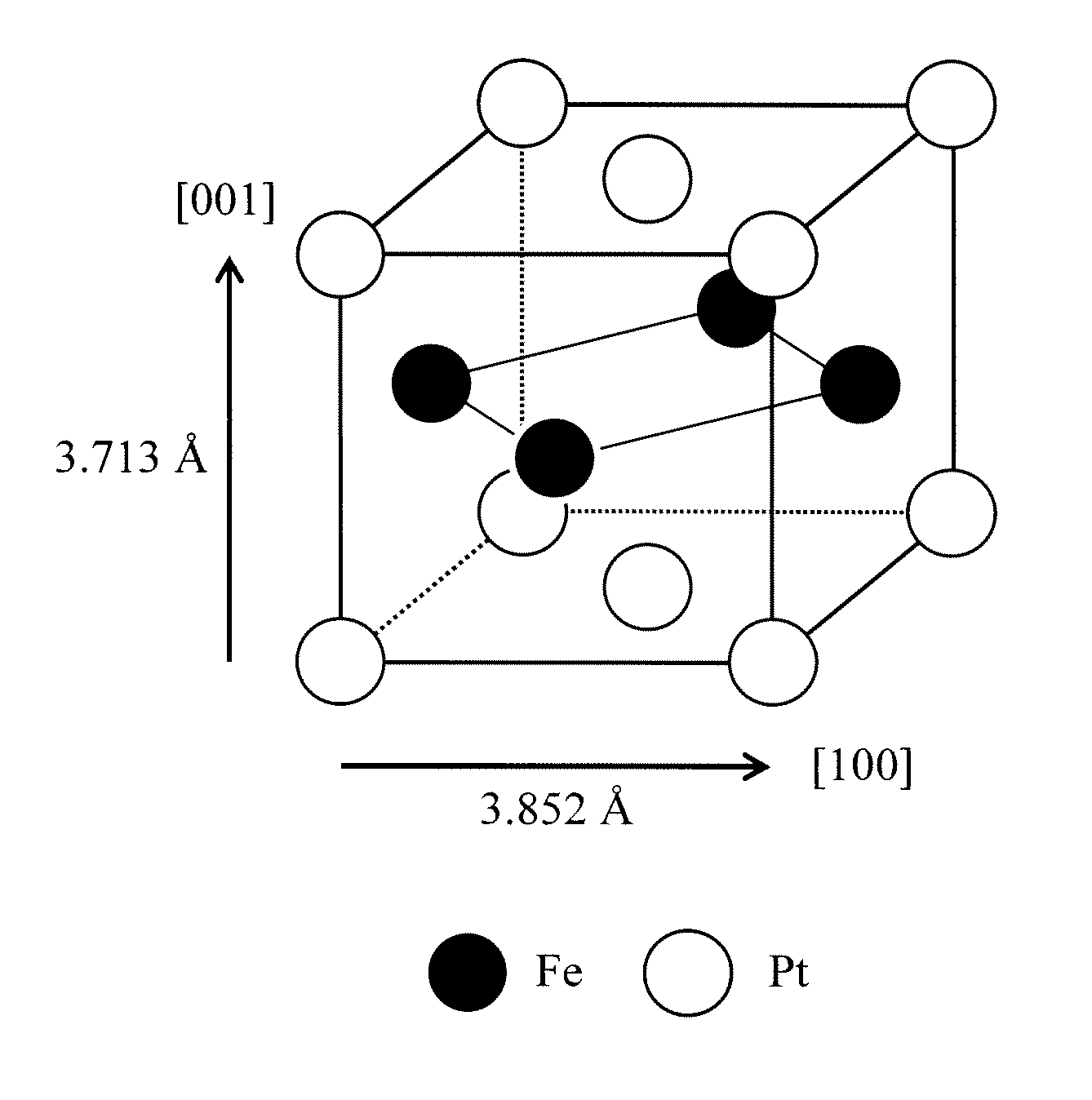
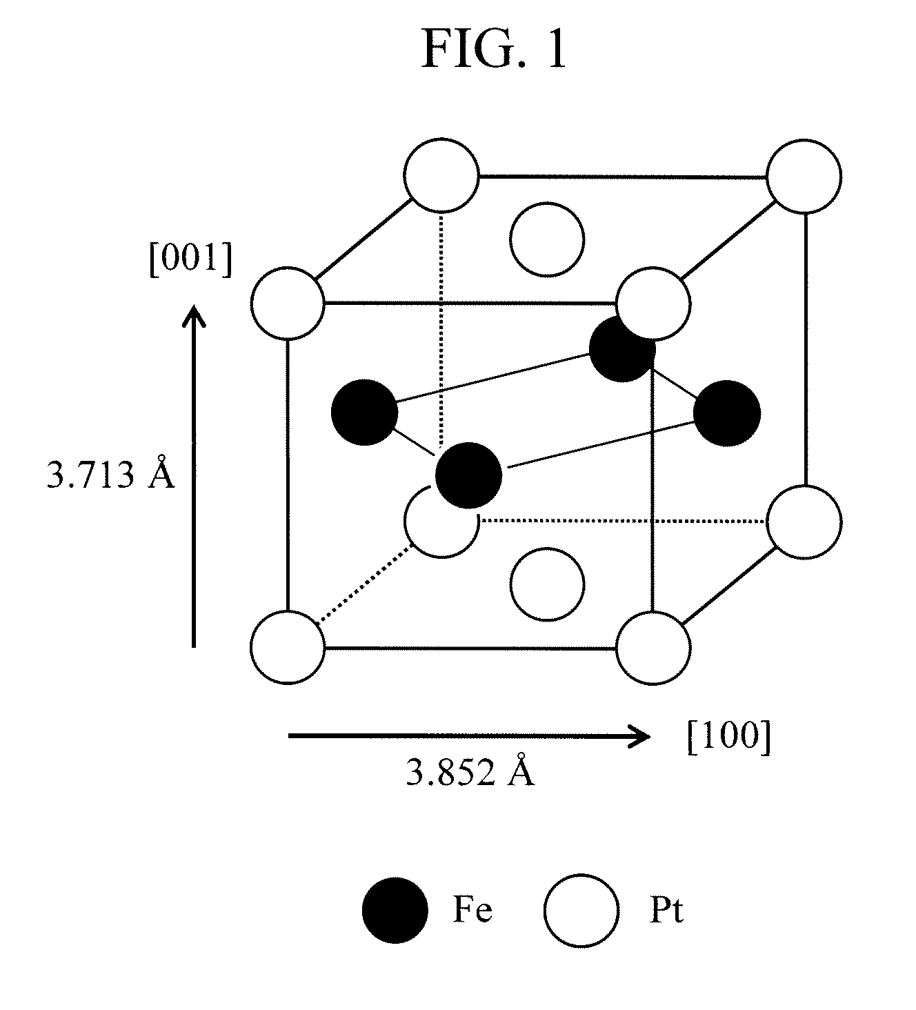
[0052]The magnetic recording medium 10 was manufactured in such a manner that a heat-resistant glass was used to form the substrate 100; an Ni—Ta layer with a thickness of 100 nm was formed thereon as the adhesion layer 110; a strontium titanate layer with a thickness of 12 nm was formed thereon as the conductive compound layer 120; the MgO underlayer 130 with a thickness of 1 nm was formed thereon; a 70 vol % (45 at % Fe-45 at % Pt-10 at % Ag)-30 vol % C layer with a thickness of 6 nm was formed thereon as the magnetic recording layer 140; and a carbon nitride layer with a thickness of 4 nm was formed thereon as the overcoat 150 in a sequential manner. The time required to form the MgO underlayer 130 with a thickness of 1 nm was 2.0 seconds.

[0053]An inline high-speed disk sputtering system (C-3010) manufactured by Canon ANELVA Corporation for use in mass production of a magnetic recording medium for a hard disk drive was used to manufacture the magnetic recording mediu...

Example

Second Example

[0061]The second example of the present invention used the same method as that of the first example except that the thickness of the MgO underlayer 130 was variously changed to manufacture a plurality of magnetic recording media 10. The characteristics of these magnetic recording media 10 were evaluated by the same method as that of the first example.

[0062]FIG. 6 is graphs plotting the saturation magnetization, the coercivity, the magnetic anisotropy constant, the order parameter, the crystalline orientation randomness, and the grain diameter of the magnetic recording media 10 according to the second example with respect to the thickness of the MgO underlayer 130. Here, the crystalline orientation randomness is defined as a diffraction peak intensity from the (111) crystal plane normalized by a diffraction peak intensity from the (002) crystal plane in the X-ray diffraction pattern. A larger value means that the film surface perpendicular orientation of the [001] axis ...

Example

Third Example

[0069]The third example of the present invention used the same method as that of the first example except that a Cr layer with a thickness of 7 nm was added and formed as the orientation control layer between the adhesion layer 110 and the conductive compound layer 120 to manufacture the magnetic recording medium 10. The characteristics of this magnetic recording medium 10 were evaluated by the same method as that of the first example.

[0070]The first to second rows of FIG. 7 list the values of the coercivity, the magnetic anisotropy constant, and the crystalline orientation randomness of the magnetic recording media 10 according to the first example and the third example respectively. In the case of the magnetic recording medium 10 according to the first example (first row), a very small amount of diffraction peak from the (111) crystal plane of the FePt alloy was observed, while in the case of the magnetic recording medium 10 according to the third example, the diffrac...


PUM


Abstract

There is provided a magnetic recording medium including an MgO underlayer that can be formed by a mass production process and has a thickness of 3 nm or less as well as including a magnetic recording layer made of an L10-type FePt ordered alloy having excellent magnetic properties. A conductive compound having a crystal structure belonging to a cubic system is used as a material of an underlayer provided at the bottom of the MgO underlayer. The thickness of the MgO layer is 1 nm or more and 3 nm or less.

Description

CLAIM OF PRIORITY[0001]The present application claims priority from Japanese patent application JP 2011-037408 filed on Feb. 23, 2011, the content of which is hereby incorporated by reference into this application.BACKGROUND OF THE INVENTION[0002]1. Field of the Invention[0003]The present invention relates to a magnetic recording medium.[0004]2. Background Art[0005]A large capacity magnetic recording apparatus, namely, a high density magnetic recording medium has been achieved by decreasing the size of ferromagnetic crystal grains forming a magnetic recording layer of the magnetic recording medium. However, when the size of ferromagnetic crystal grains are decreased, the magnetic anisotropy energy (the product of the magnetic anisotropy energy per unit volume (magnetic anisotropy constant) of the ferromagnetic crystal grains and the volume of the ferromagnetic crystal grains) of the ferromagnetic crystal grains is small relative to the atomic thermal vibration energy (product of the...

Claims


Application Information

Patent Timeline
IPC IPC(8): G11B5/65
CPCG11B5/7325G11B5/65G11B5/737G11B5/7375
Inventor SAYAMA, JUNICHITAKEKUMA, IKUKONEMOTO, HIROAKI
Owner HITACHI LTD
Why Eureka
Try Eureka