Exposure method, exposure apparatus, and method for producing device

Inactive Publication Date: 2006-10-24
NIKON CORP
View PDF47 Cites 26 Cited by
  • Summary
  • Abstract
  • Description
  • Claims
  • Application Information

AI Technical Summary

Benefits of technology

[0101]A method for producing a device according to the present invention comprises a step of transferring a mask pattern onto a workpiece by using any one of

Problems solved by technology

However, the method, in which the respective stage systems, the stage chambers, and other components are successively assembled with respect to the single flame mechanism as described above, requires a considerable period of time to assemble and adjust the apparatus.
Further, a long period of time is required, for example, to adjust the relative positions between the respective stage systems and the projection optical system.
Therefore, an inconvenience arises such that the production cost of the exposure apparatus is increased.
Further, the method, in which the respective stage s

Method used


Image

  • Exposure method, exposure apparatus, and method for producing device
  • Exposure method, exposure apparatus, and method for producing device
  • Exposure method, exposure apparatus, and method for producing device

Examples


Example

[0144]An exemplary embodiment of the present invention will be explained below with reference to the drawings. In this embodiment, the present invention is applied to a projection exposure apparatus of the scanning exposure system based on the step-and-scan system.

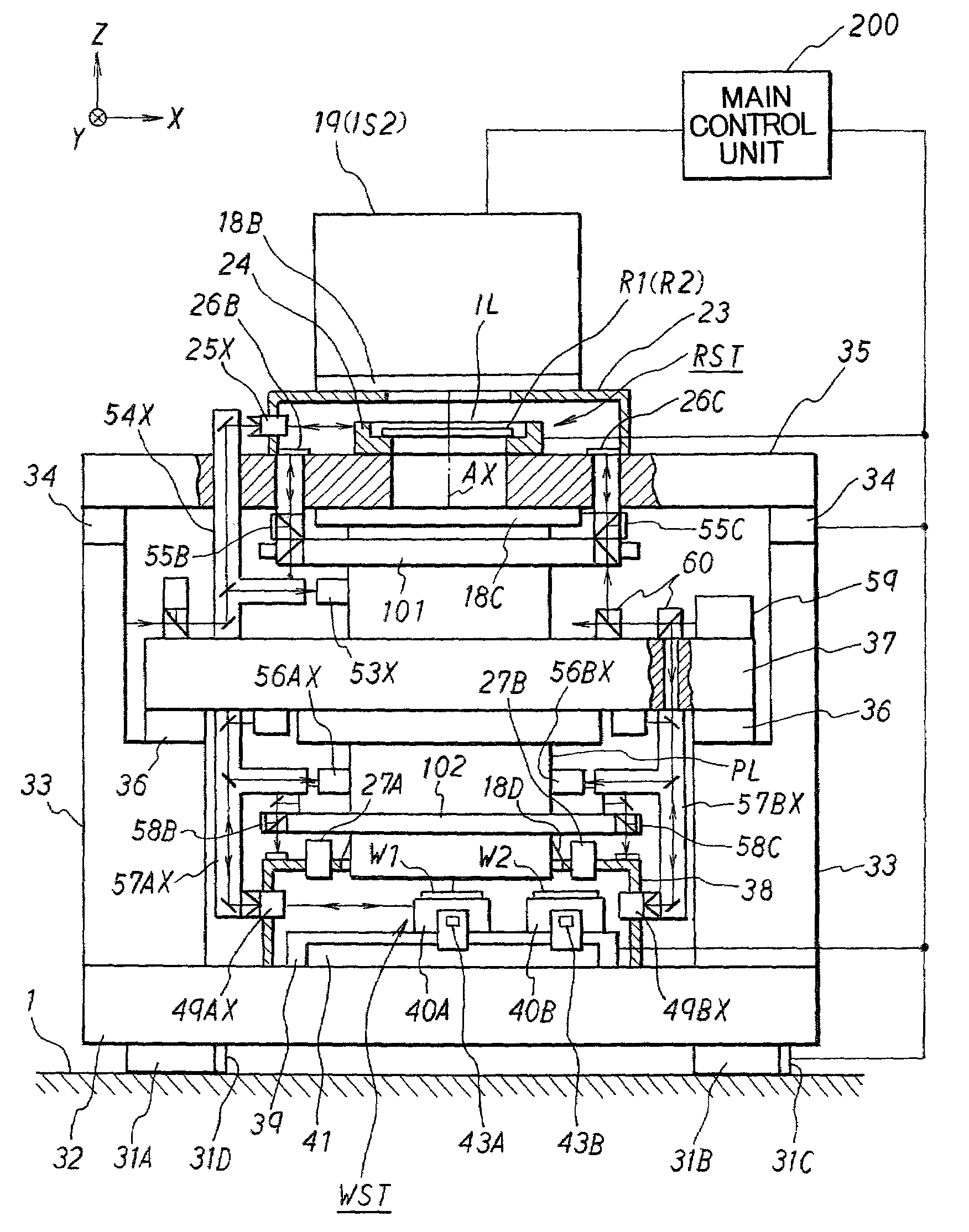
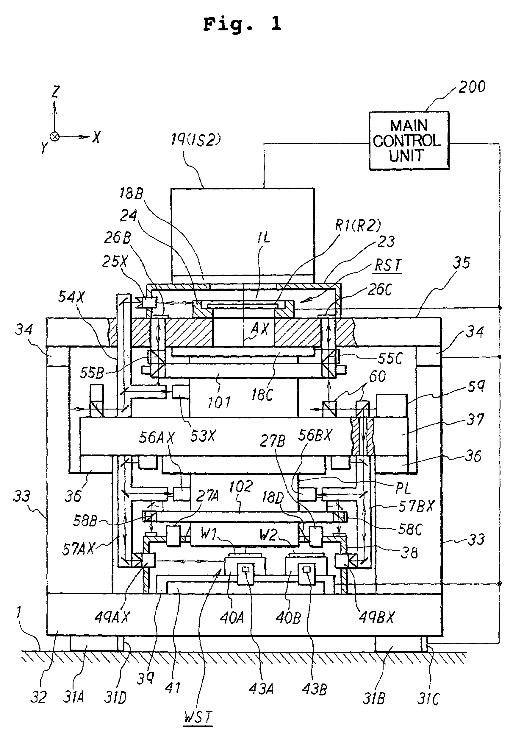
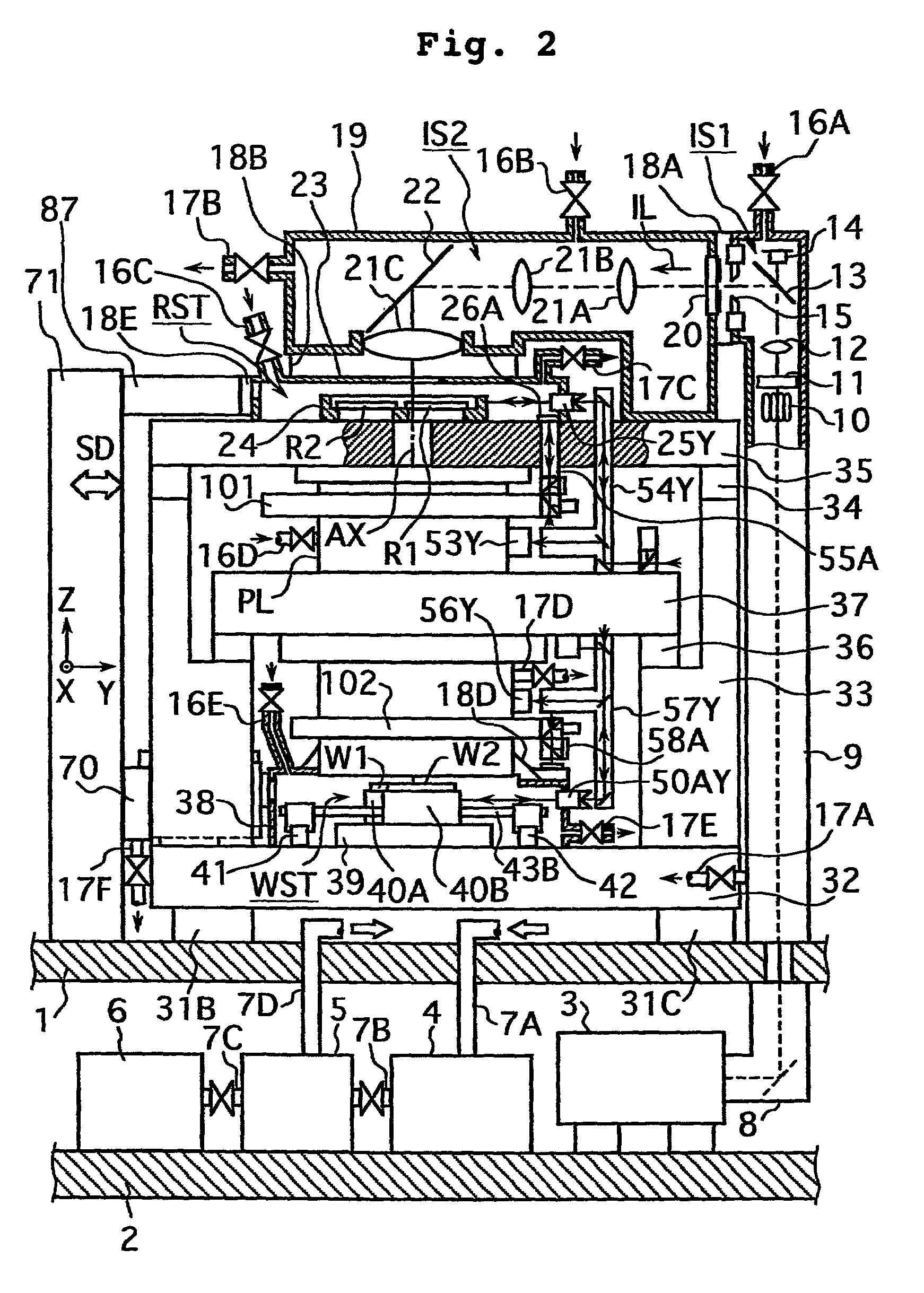
[0145]FIG. 1 shows a front view illustrating the projection exposure apparatus according to this embodiment, and FIG. 2 shows a side view illustrating the projection exposure apparatus. With reference to FIGS. 1 and 2, for example, the major portion of the projection exposure apparatus of this embodiment is installed in a clean room on a floor 1 of a semiconductor-producing factory. An exposure light source 3 of the projection exposure apparatus is installed on a floor 2 in a semi-clean room of a machine room disposed under the floor 1. An ArF excimer laser light source (wavelength: 193 nm) is used as the exposure light source 3. However, it is also possible to use other light sources for emitting the vacuum ultraviolet li...


PUM


Abstract

An exposure apparatus for exposing a substrate with an exposure light beam passing through a mask comprises a movable stage for moving the substrate, a stage chamber for accommodating the movable stage, a transport system for transporting the substrate into the stage chamber, and a first alignment system for performing positional adjustment for the substrate with respect to the movable stage in the stage chamber. The position of an exposure objective delivered from the transport system into the stage chamber can be subjected to positional adjustment by using the first alignment system. The stage chamber and the movable stage can be assembled to a frame of the exposure apparatus in accordance with the module system. The exposure apparatus includes a second alignment system for performing positional adjustment for the substrate installed on the movable stage at an exposure position.

Description

BACKGROUND OF THE INVENTION[0001]1. Field of the Invention[0002]The present invention relates to an exposure method and an exposure apparatus to be used when a mask pattern is transferred onto a substrate in the lithography step for producing devices including, for example, semiconductor elements, liquid crystal display elements, plasma display elements, and thin film magnetic heads. The present invention also relates to techniques in relation to the above.[0003]2. Description of the Related Art[0004]High exposure accuracy is required for the exposure apparatus of the full field exposure type (stepper type) or the scanning exposure type (for example, the step-and-scan system) to be used in order to produce semiconductor elements or the like. Therefore, the exposure apparatus adopts arrangements which make it possible to perform highly accurate positioning or highly accurate scanning for the reticle stage system for positioning the reticle as a mask and for the wafer stage system for...

Claims


Application Information

Patent Timeline
IPC IPC(8): G01B11/00G01B11/14G03B27/32G03B27/42G03F9/00G01B11/02G03F7/20H01L21/027
CPCG03F7/70733G03F7/7075G03F7/70866G03F9/7011H01L21/027
Inventor NISHI, KENJI
Owner NIKON CORP
Why Eureka
Try Eureka