Sub tragic ear unit

a technology of ear unit and ear plug, which is applied in the direction of ear plugs, intra-aural earpieces, applications, etc., can solve the problems of difficult to exclude ambient sounds, long-term discomfort, and large size, and achieve the effect of stable positioning in the ear and reduced deformation

Active Publication Date: 2015-07-30
FREEBIT AS
View PDF15 Cites 44 Cited by
  • Summary
  • Abstract
  • Description
  • Claims
  • Application Information

AI Technical Summary

Benefits of technology

[0031]The technical differences over prior art is that a sub-tragus system is provided wherein the attachment is provided by an anchor and not by any elements protruding into the ear canal.
[0037]it enables stable positioning in the ear without exerting uncomfortable pressure against the concha
[0040]it allows for air circulation.
[0041]The technical differences over prior art is that the anchor does not fill the entire concha but instead comprises two branches, the first branch falls along the inner part of the antihelix and the second branch extends into an extended lower end which is partly positioned under the tragus. Normally, when a force is applied to the concha in the downward direction when a person is standing up, the concha will deform slightly by elongating in the direction of the force and narrowing in a direction perpendicular to said force, thus the tragus and antitragus comes closer. However with the anchor according to this invention inserted the two branches will resist the narrowing. At the same time the force is distributed across a large area.
[0045]the reduced deformation allows for larger load bearing without discomfort than means that permit deformation of the concha

Problems solved by technology

While the solution is compact, removes ambient sound efficiently and also allows for good audio fidelity it suffers from the disadvantage of being uncomfortable due to pressure exerted on the pressure sensitive ear canal.
This solution is simple but suffers from long term discomfort due to pressure exerted on the ear by the means for holding.
There can also be problems with ambient sound entering the ear unless a sound absorbing cushion is used that encloses the ears fully bringing in other disadvantages such as large size.
While compact the disadvantage is discomfort due to pressure exerted on the tragus and anti tragus and also that it is difficult to exclude ambient sounds.
If the pressure against the tragus and anti tragus is reduced the ear bud then is rather loose and can easily fall out.
The problem is stable positioning of the hearing element and discomfort relating to the edge of the hearing element is pressed against the inner wall of the concha when positioned in the ear.

Method used


Image

  • Sub tragic ear unit
  • Sub tragic ear unit
  • Sub tragic ear unit

Examples


first embodiment

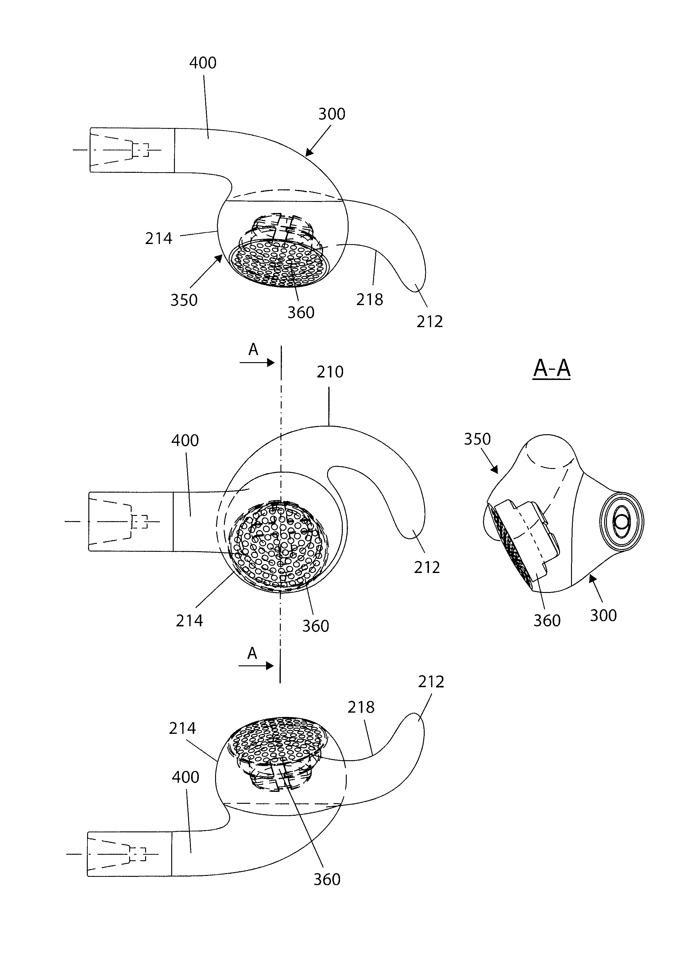
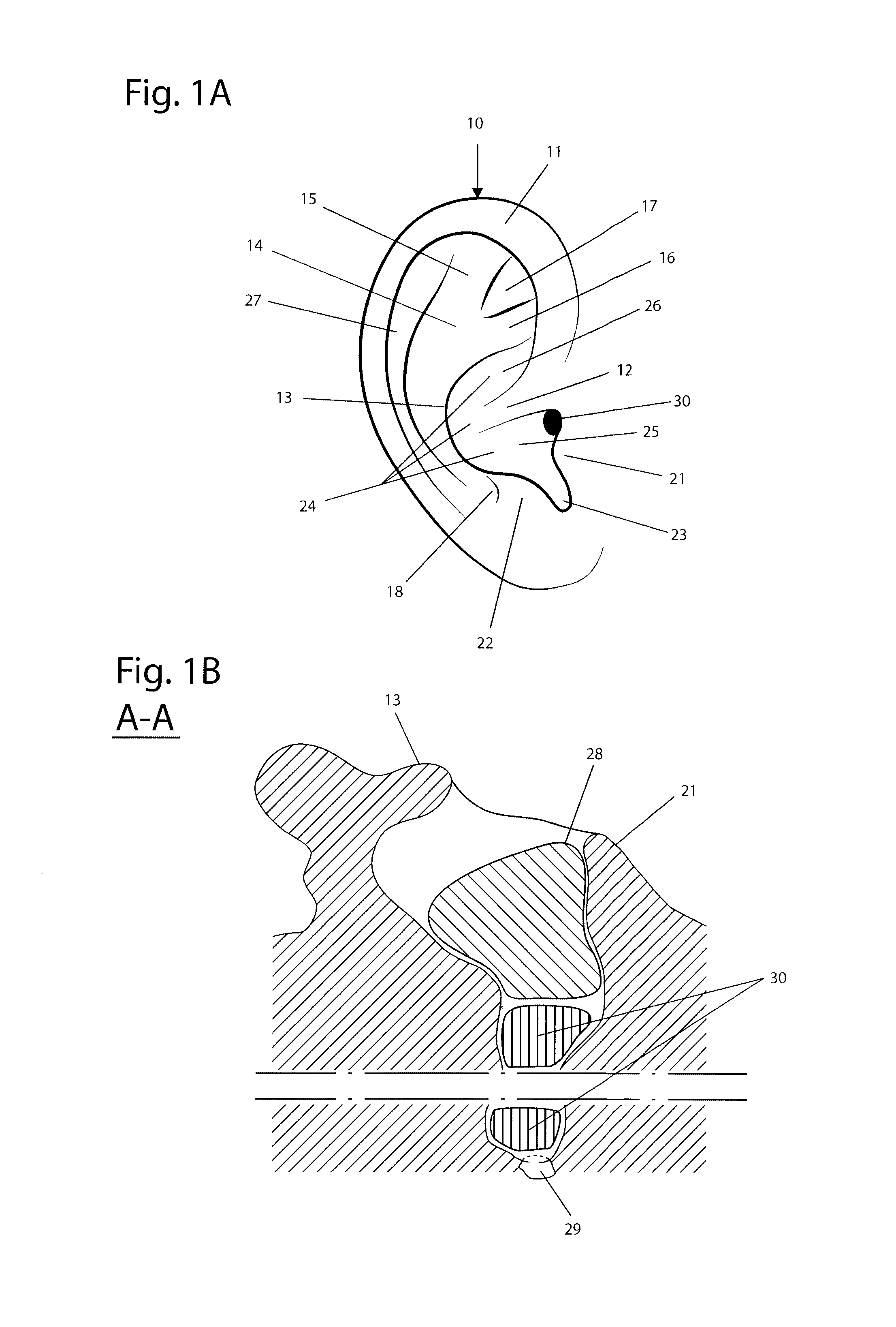
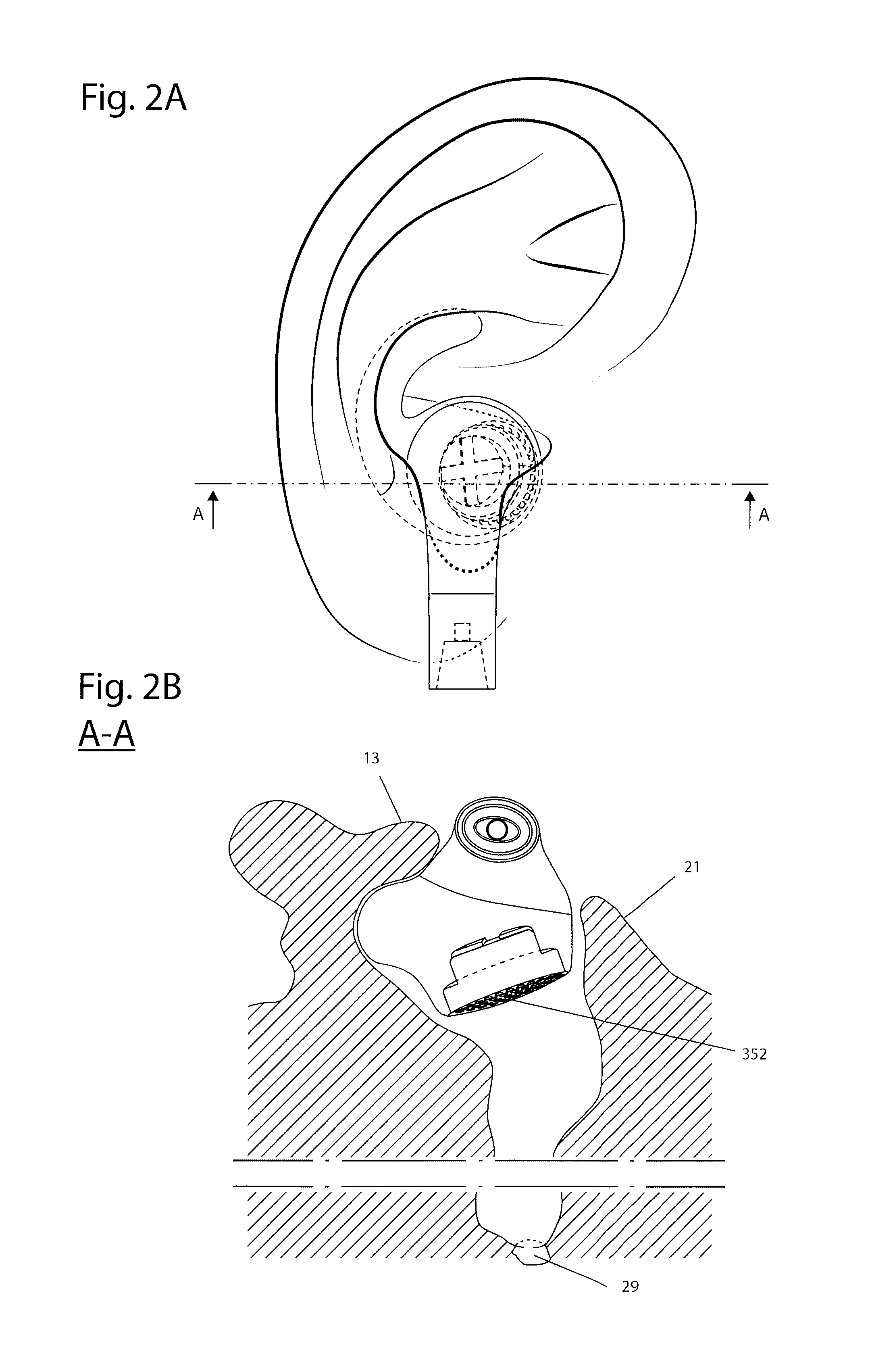
[0066]In a first embodiment a hearing element 350 in the form of an electro acoustic transducer 360 is positioned underneath the tragus. Said hearing element is dimensioned to fit in the sub-tragus region. FIG. 2B shows schematically the above construction.

second embodiment

[0067]In a second embodiment the hearing element 350 comprises an electro acoustic transducer 360 attached to an audio duct 354 provided with an audio duct opening 356. As long as the audio duct is smaller than the wavelength of the sound, having a frequency of typically 20 Hz to 20000 Hz, corresponding to a wavelength of 15 m to 15 mm respectively, sound is conducted without significant distortion and the effective aperture becomes the opening of the audio duct.

[0068]This second embodiment allows for having the electro acoustic transducer larger than that of the first embodiment by retracting it away from the tragus. Since the effective hearing element is the end of the funnel and that this end projects into the sub-tragus region the technical effect is the same as for the first embodiment FIG. 2C shows schematically the above construction.

[0069]This second embodiment also allows for the electro acoustic transducer to be oriented at an angle that is not parallel to the plane of the...


PUM


Abstract

A sub-tragus ear unit for comfortable wear of an in-ear ear unit is provided. The sub-tragus ear unit achieves the technical effect by separating the earphone from the attachment functionality that is provided by a separate anchor, wherein the earphone is attached to said anchor.

Description

BACKGROUND OF THE INVENTION[0001]1. Technical Field[0002]The invention relates to a system for removable ear attachment in general and in particular a sub-tragus ear unit for comfortable attachment of an ear unit.[0003]2. Background Art[0004]Microphone / earpiece combinations, wireless or attached by wire, to telephones, music systems, switchboards etc. are well known. A wide variety of solutions exist.[0005]One solution is known as the “in-ear” solution, wherein the sound emitting device, also known as a hearing element, enters the ear canal. Typically a housing unit comprising a hearing element is positioned inside the concha and within the tragus and anti tragus, while a funnel ducts the sound into the ear canal. Frequently the funnel is provided with a gasket having flanges to dampen ambient sounds.[0006]Typically such devices use the ear canal for attachment. While the solution is compact, removes ambient sound efficiently and also allows for good audio fidelity it suffers from t...

Claims


Application Information

Patent Timeline
Patent Type & Authority Applications(United States)
IPC IPC(8): H04R1/10
CPCH04R1/10A61F11/08H04R1/1016H04R1/105H04R2460/09H04R1/1083H04R2201/107H04R2460/11A44C7/004H04R25/656H04R1/2869H04R1/02
Inventor SANDANGER, VIDAR
Owner FREEBIT AS
Why Eureka
Try Eureka