Loudspeaker protection systems and methods

a loudspeaker and protection system technology, applied in the direction of transducer details, electrical transducers, signal processing, etc., can solve the problems of thermal overload of the loudspeaker, audio drive circuitry overloading the loudspeaker, and not always economical,

Active Publication Date: 2015-07-30
CIRRUS LOGIC INC
View PDF5 Cites 49 Cited by
  • Summary
  • Abstract
  • Description
  • Claims
  • Application Information

AI Technical Summary

Benefits of technology

[0011]Embodiments of the present invention provide methods and apparatus for speaker

Problems solved by technology

However having robust enough loudspeakers is not always economical, and for portable devices in particular the desire is typically to make the speaker as small and light as possible.
This can potentially lead to the audio drive circuitry overloading the loudspeaker.
One particular problem is thermal overload of the loudspeaker.
One particular problem to be avoided is overheating of the voice coil which could result in degradation in performance and/or damage to the loudspeaker.
As mentioned above ohmic power losses can result in heating of the voice coil and thus an increase in the voice coil temperature Tvc.
This approach however requires assumptions about the thermal resistances of the voice coil and magnet and the worst case maximum ambient temperature.
This will typically lead to conservative values being assumed which may lead to limiting

Method used


Image

  • Loudspeaker protection systems and methods
  • Loudspeaker protection systems and methods
  • Loudspeaker protection systems and methods

Examples


Embodiment Construction

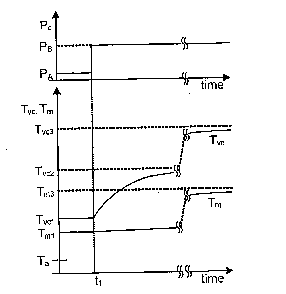
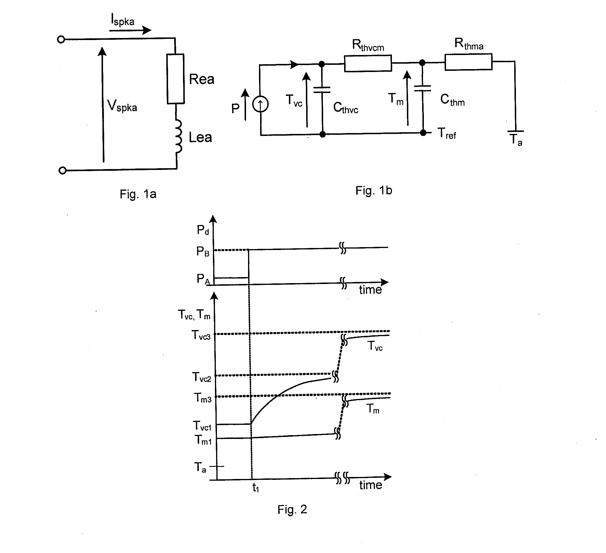
[0061]As mentioned above FIG. 1b illustrates a thermal model of a typical loudspeaker which explains how the output power from the audio driving circuitry can lead to an increase in the temperature of the voice coil. It will be understood that the various thermal time constants for the components of the model, i.e. the components of the loudspeaker may be quite different.

[0062]Audio signals are conventionally in the range of about 20 Hz-20 kHz with corresponding time constants of the order of 10 ms to 10 μs. The output audio power is usually determined over a plurality of cycles of the instantaneous audio signal but still within a period typically less than about 100 ms or so. It will be appreciated that for an audio track the amplitude of the input signal, i.e. the relative loudness of the intended sound signal, may vary throughout the track. For instance an audio track may have relatively louder and relatively quieter periods and may transition from quiet to loud, or vice versa, r...


PUM


Abstract

Methods and systems for thermal protection of a voice coil of a loudspeaker. The method involves driving the loudspeaker based on an input signal received at an input terminal and monitoring both a voltage applied to the voice coil and a current flowing through the voice coil. From the monitored voltage and current, an estimate of temperature of the voice coil and an estimate of power dissipation in the voice coil is determined. The method includes estimating the voice coil resistance based on the monitored voltage and current and at least the estimate of temperature is determined based the estimate of resistance. A gain control signal for modulating a gain applied to the input signal is generated as a function of both the estimate of temperature of the voice coil and the estimate of power dissipation in the voice coil. This means that high power dissipation, which would over long periods lead to overheating, can nevertheless be permitted when the voice coil temperature is low enough, while at high voice coil temperatures any gain modulation applied for thermal protection can be reduced if the power dissipation level drops.

Description

BACKGROUND OF THE INVENTION[0001]1. Field of the Invention[0002]This invention relates to methods and apparatus for protecting loudspeakers, and especially to methods and apparatus for controlling the drive signal supplied to the loudspeaker so as to avoid over-temperature operation.[0003]2. Description of the Related Art[0004]A number of different products include audio circuitry, such as an audio amplifier, together with one or more loudspeakers and / or connections for driving one or more loudspeakers of a peripheral apparatus such as a headset. In some instances the loudspeaker(s) chosen will be robust enough and large enough to handle the maximum power level at which the amplifier could drive signals continuously into it, even under the worst case environmental conditions, for instance maximum supply voltage, maximum ambient temperature etc. However having robust enough loudspeakers is not always economical, and for portable devices in particular the desire is typically to make t...

Claims


Application Information

Patent Timeline
IPC IPC(8): H04R9/02H04R3/00
CPCH04R3/00H04R9/022H04R3/007H04R29/003H04R2430/01
Inventor MAGRATH, ANTHONYNAPOLI, ROBERTO
Owner CIRRUS LOGIC INC
Why Eureka
Try Eureka