Roll for a roller grinder, and roller grinder comprising such roll

a technology of roller grinder and roller, which is applied in the direction of manufacturing tools, grain treatment, cocoa, etc., can solve the problems of high pressure roller grinder for grinding, interruption of equipment operation, and high level of wear of processed materials, so as to achieve easy mounting and dismounting, and reduce costs

Inactive Publication Date: 2015-08-06
METSO BRASIL IND E COMML LTDA
View PDF0 Cites 7 Cited by
  • Summary
  • Abstract
  • Description
  • Claims
  • Application Information

AI Technical Summary

Benefits of technology

[0008]It is an object of the present invention to solve, fully or partially, the above problems and to provide an improved roll for a roller grinder having an outer grinding shell that is easy to mount and dismount, so as to reduce costs when exchanging worn down grinder shells, while still providing a grinding shell that does not loosen during operation of the grinder.
[0010]According to the present invention the grinding shell of the roll for a roller grinder is segmented in a plurality of grinding shell segments, which results in a grinding shell that is divided into smaller pieces. A benefit from this is that the grinding shell may be easier to manufacture than a one piece grinding shell. Moreover, such a grinding shell is easier to transport and handle. It is easier to transport and handle the big grinding shell in pieces than transporting and handling the one piece grinding shell. Furthermore, since it is easier to manufacture and transport the grinding shell according to this invention a bigger number of manufactories will be available. Moreover, when mounting the grinding shell to the shaft a smaller lifting device is needed as compared with mounting the one piece grinding shell. By securing the grinding shell segment to the shaft by a wedging arrangement it is easy to assemble and disassemble the grinding shell. Moreover, by securing the grinding shell segment to the shaft by the use of the wedging arrangement a preload between the grinding shell segment and the support structure of the shaft may be applied. By arranging the wedging device in a channel extending axially along said shaft the wedging force applied by the wedging device may be distributed over the whole contact surface between the supporting structure and the grinding shell segment. Especially, a preload between the grinding shell segment and the support structure of the shaft may be applied which is sufficient to support the segment, this assuring a strong permanent contact between grinding shell segment and the support structure of the shaft. The strong permanent contact between grinding shell segment and the support structure of the shaft minimizes the wear between the grinding shell segment and the support structure of the shaft. Thus, the lifetime of the grinding shell segments and the support structure is extended. By releasably securing the grinding shell segment to the support structure of the shaft by the wedging device it is easy to dismount the grinding shell segment from the support structure of the shaft. Thus, it is easy to exchange a worn down grinding shell by usage of the roll in a roller grinder.
[0012]Each channel may have an axial extension along said shaft being essentially as long as the associated grinding shell segment. Each wedging device may further be arranged to apply a wedging force along essentially the whole axial extension of the associated grinding shell segment. This ensures that the wedging force applied by the wedging device is distributed over the whole contact surface between the supporting structure and the grinding shell segment, ensuring a strong permanent contact between the grinding shell segment and the support structure minimizing the wear between the grinding shell segment and the support structure of the shaft.

Problems solved by technology

High pressure roller grinders for grinding rock and the like are for obvious reasons subjected to a high level of wear from the processed material.
The grinder shell eventually has to be replaced when worn down by the processed material, causing an interruption of the operation of the equipment.
This known mounting solution presents some inconveniences.
The outer grinding shell can crack upon cooling, particularly when it is made of hard high carbon steel.
The mounting solution by thermal expansion-contraction of the outer grinding shell also presents inconveniences when dismounting the grinding shell from the hub portion of the shaft.
The dismounting is extremely difficult due to the high level of frictional interference between the two parts.
This difficulty is so great and time consuming that it is frequently preferred to replace the whole shaft-grinding shell assembly, undesirably increasing the costs of replacing the already worn out grinding shells.
This problem is particularly cost inducing when the frequency of these replacements is high due to a high level of wear of the outer shell.
It is also frequent, in such cases, that the shaft is damaged during the dismounting procedure, further increasing the replacement costs of the grinding shell.
In many cases, the bearings, which are usually an expensive part, are integrated in the shaft assembly, further increasing the cost of the replacement when not being able to dismount the outer shell.
In general, use of a one-piece grinding shell leads to difficulties when replacing a worn roll, since the shaft, the grinding shell, and the bearings have to be removed from the machine, thereby necessitating disconnection of the drive system, the feed chute, etc.
However, due to the long distance between the fixation points, material will enter between the grinding shell and the support structure and start wearing down the interface surface between the grinding shell and the support structure during operation of the roll.
This wear will limit the lifetime of the grinding shell segments as well as the lifetime of the support structure.
Moreover, high and uneven forces will move the segments of the grinding shell in relation to the support structure also limiting the lifetime of the grinding shell segments and the support structure.

Method used


Image

  • Roll for a roller grinder, and roller grinder comprising such roll
  • Roll for a roller grinder, and roller grinder comprising such roll
  • Roll for a roller grinder, and roller grinder comprising such roll

Examples


Embodiment Construction

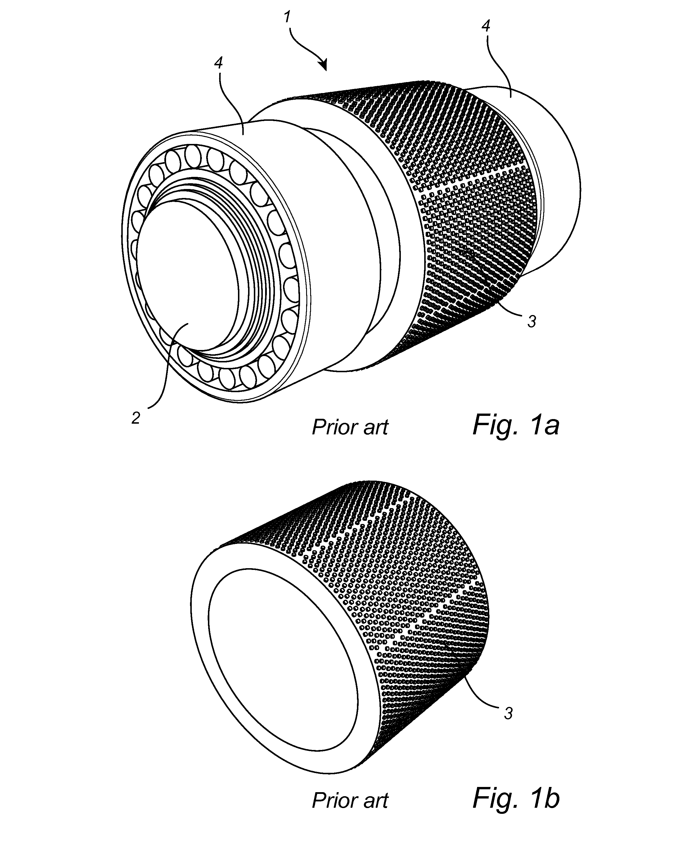
[0033]FIG. 1a shows one of the rolls 1 in a high pressure roller grinder (not fully shown) according to prior art. The roll 1 comprises a shaft 2 and a grinding shell 3 in the form of a generally tubular sleeve. The grinding shell 3 surrounds a hub of the shaft 2. The shaft 2 is held in the roller grinder by two bearings 4. For high pressure roller grinders it is not unusual for the roll to weigh in the order of 100 tons, wherein the grinding shell itself weighs in the order of 10 tons.

[0034]FIG. 1b shows the grinding shell 3 as shown in FIG. 1a when not being mounted on the shaft.

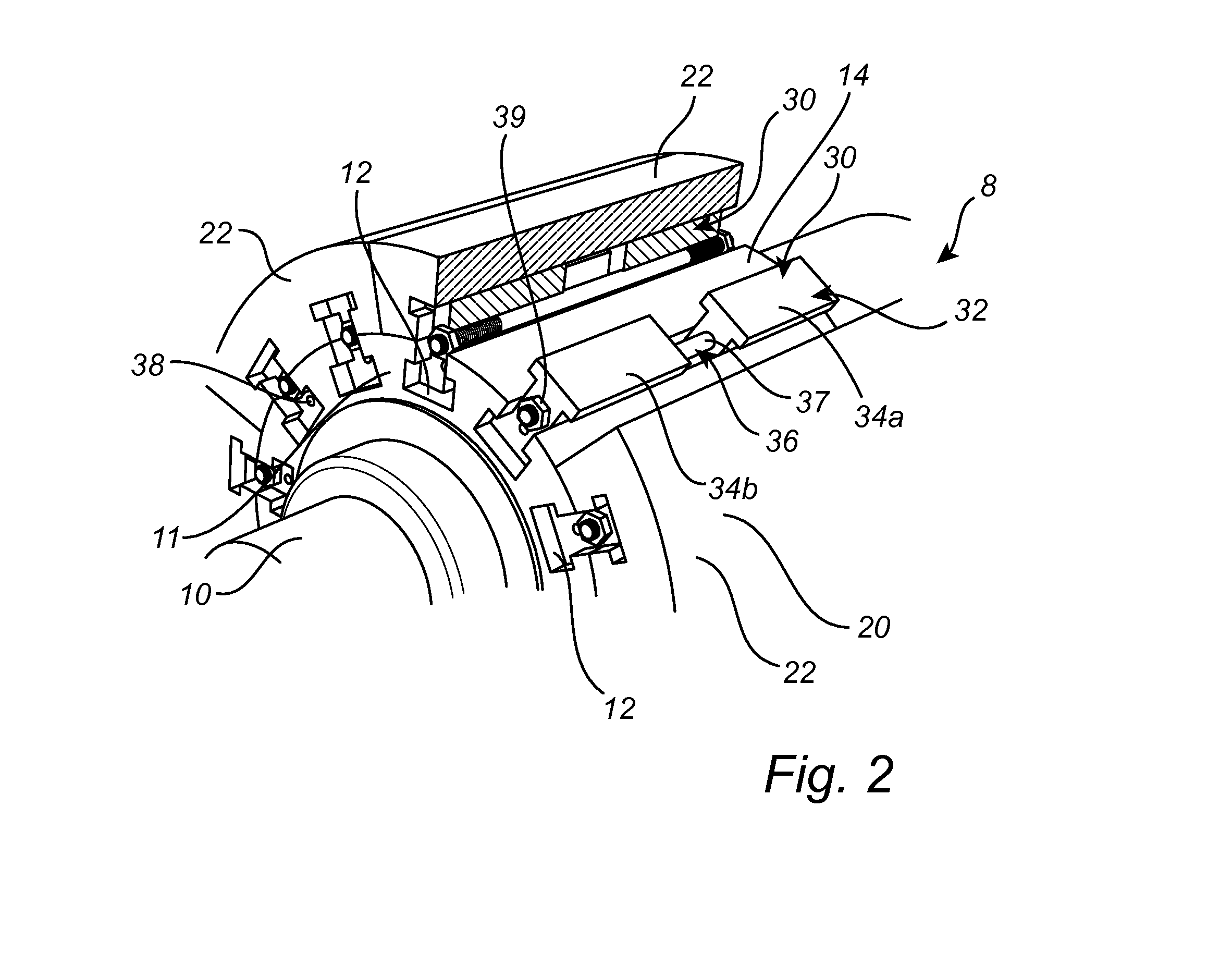
[0035]With reference to FIG. 2-7 a preferred embodiment of a roller grinder (not fully shown) according to the present invention will be described.

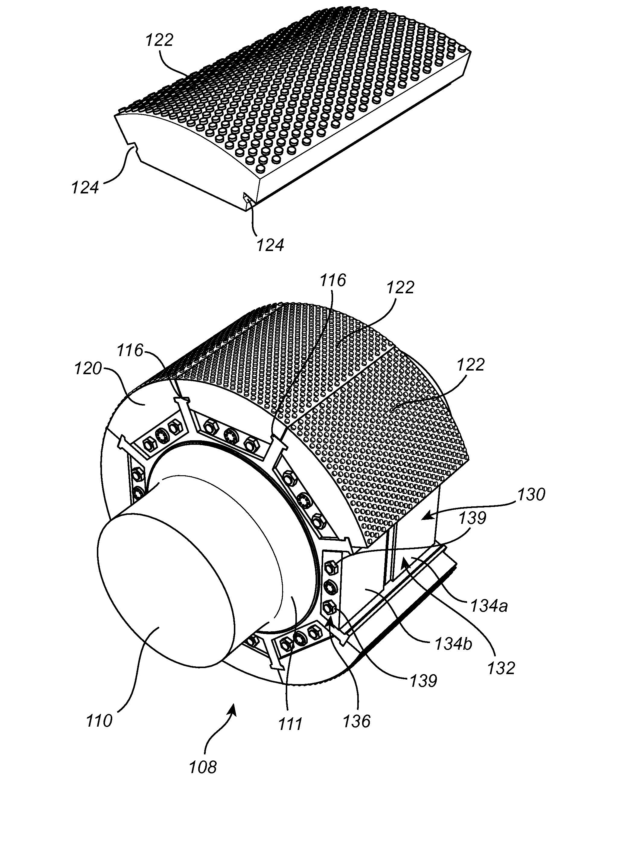
[0036]FIG. 2 shows a part of a roll 8 in a preferred embodiment of a roller grinder (not fully shown) according to the present invention. The roll 8 comprises a shaft 10, the shaft 10 being held in the roller grinder by two bearings (not shown). Moreover, the ro...


PUM


Abstract

The present disclosure relates to a roll for a roller grinder. The roll includes a shaft having a support structure; a plurality of grinding shell segments circumferentially arranged around the shaft to form a tubular grinding shell supported by the support structure; and a wedging device for each grinding shell segment. Each wedging device is arranged in a channel extending axially along the shall and defined by the associated grinding shell segment and the support structure. Each wedging device is arranged to releasably secure the grinding shell segment to the support structure. The present disclosure also relates to a high pressure grinder including the above roll.

Description

TECHNICAL FIELD OF THE INVENTION[0001]The present invention relates to a roll for a roller grinder, the roll comprising a shaft and a grinding shell in the form of a generally tubular sleeve. The invention further relates to a high pressure roller grinder.BACKGROUND ART[0002]High pressure roller grinders for grinding rock and the like are for obvious reasons subjected to a high level of wear from the processed material. Each roll of a roller grinder therefore commonly utilizes an outer cylindrical grinder shell made of a wear resistant material covering the rolls. The grinder shell eventually has to be replaced when worn down by the processed material, causing an interruption of the operation of the equipment.[0003]The grinding or crushing shell has to be tightly mounted around a hub portion of the shaft, with a high friction between the parts to avoid loosening of the shell during operation of the grinder. The hub portion of the shaft may have a cylindrical shape or may be slightly...

Claims


Application Information

Patent Timeline
Patent Type & Authority Applications(United States)
IPC IPC(8): B02C4/30
CPCB30B11/165B02C4/30
Inventor NIKLEWSKI, ANDRZEJBARSCEVICIUS, PAULO
Owner METSO BRASIL IND E COMML LTDA
Why Eureka
Try Eureka