Insulated glazing and method of producing insulated glazing

a technology of insulated glazing and insulated glazing, which is applied in the direction of transportation and packaging, other domestic objects, and units with parallel planes, etc., can solve the problem of decreasing the vacuum degree of the gap

Inactive Publication Date: 2015-08-06
ASAHI GLASS CO LTD
View PDF4 Cites 15 Cited by
  • Summary
  • Abstract
  • Description
  • Claims
  • Application Information

AI Technical Summary

Benefits of technology

[0026]According to the present invention, it is possible to provide insulated glazing that is capable of significantly reducing the effect of deformation due to a thermal stress and has a sealing structure that is relatively easy to produce. Furthermore, according to the present invention, it is possible to provide a method of producing insulated glazing that is capable of significantly reducing the effect of deformation due to a thermal stress and has a sealing structure that is relatively easy to produce.

Problems solved by technology

This is because if the sealing member has poor sealing properties, components such as air and / or moisture in the atmosphere easily enter the gap through the sealing member, thereby decreasing the degree of vacuum of the gap.

Method used


Image

  • Insulated glazing and method of producing insulated glazing
  • Insulated glazing and method of producing insulated glazing
  • Insulated glazing and method of producing insulated glazing

Examples


first embodiment

[0028]A description is given below, with reference to FIG. 3, of insulated glazing according to the present invention.

[0029]In the following description, “vacuum insulated glazing” is taken as an example of insulated glazing, and a description is given of configurations and features thereof. It is clear to a person skilled in the art, however, that the present invention is not limited to “vacuum insulated glazing” and may also be similarly provided for “non-vacuum” insulated glazing.

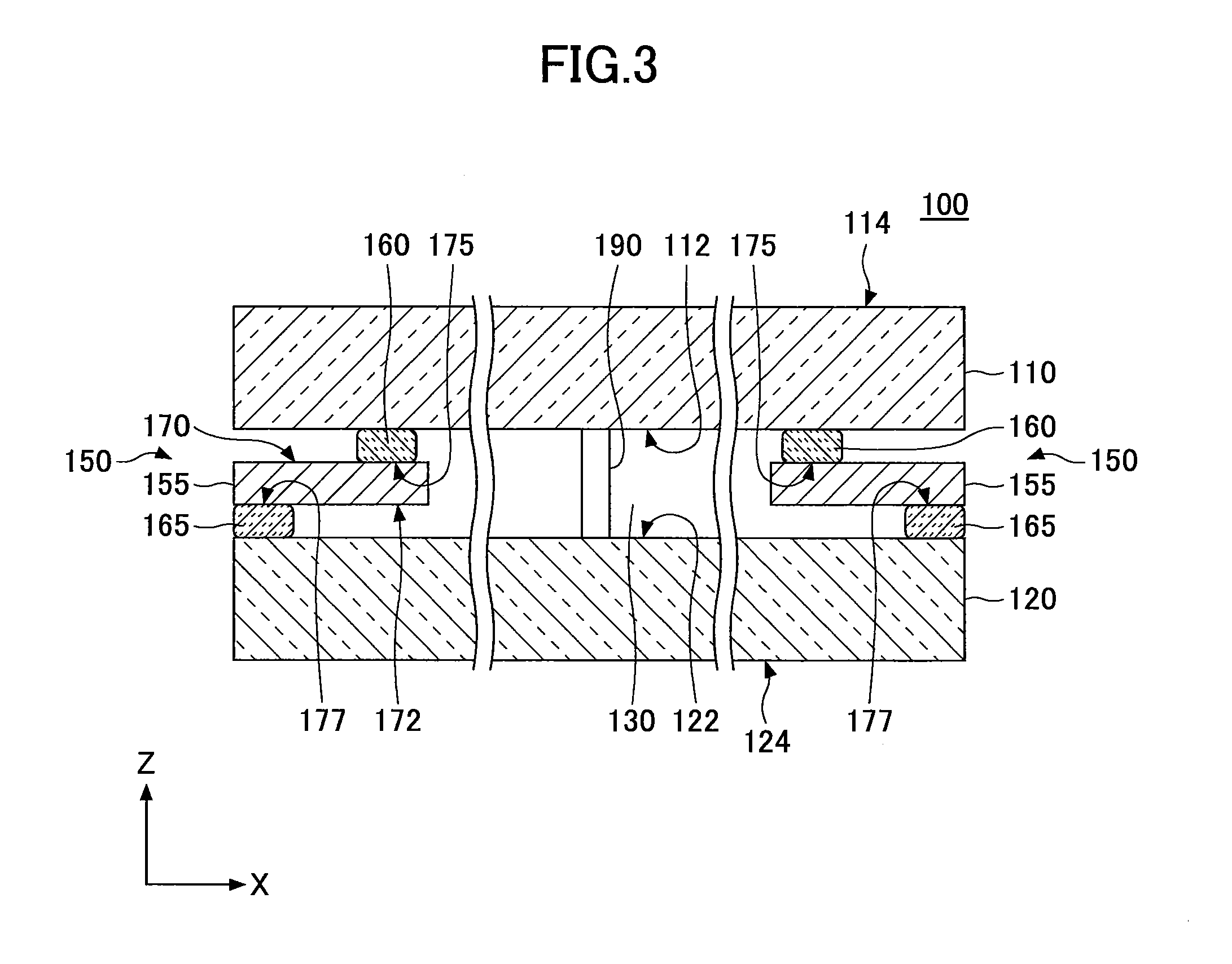
[0030]FIG. 3 schematically illustrates a configuration of vacuum insulated glazing (first vacuum insulated glazing).

[0031]As illustrated in FIG. 3, first vacuum insulated glazing 100 according to the first embodiment of the present invention includes a first glass substrate 110, a second glass substrate 120, a gap 130 formed between the glass substrates 110 and 120, multiple spacers 190 for retaining the gap 130, and a sealing member 150 that keeps the gap 130 hermetically sealed. The sealing structure 1...

second embodiment

[0062]Next, a description is given, with reference to FIG. 5, of vacuum insulated glazing according to the present invention.

[0063]FIG. 5 schematically illustrates a configuration of vacuum insulated glazing according to the second embodiment of the present invention (second vacuum insulated glazing).

[0064]As illustrated in FIG. 5, second vacuum insulated glazing 200 basically has the same configuration as the above-described first vacuum insulated glazing 100 illustrated in FIG. 3. Accordingly, in FIG. 5, the reference numerals of FIG. 3 plus 100 are used as reference numerals for the same members as those in FIG. 3.

[0065]The second vacuum insulated glazing 200 illustrated in FIG. 5, however, is different from the first vacuum insulated glazing 100 illustrated in FIG. 3 in the structure of the sealing member. That is, according to the second vacuum insulated glazing 200 illustrated in FIG. 5, a sealing member 250 includes a “stepped” metal member 255 in place of a flat metal member...

third embodiment

[0075]Next, a description is given, with reference to FIG. 6, of vacuum insulated glazing according to the present invention.

[0076]FIG. 6 schematically illustrates a configuration of vacuum insulated glazing according to the third embodiment of the present invention (third vacuum insulated glazing).

[0077]As illustrated in FIG. 6, third vacuum insulated glazing 300 basically has the same configuration as the above-described second vacuum insulated glazing 200 illustrated in FIG. 5. Accordingly, in FIG. 6, the reference numerals of FIG. 5 plus 100 are used as reference numerals for the same members as those in FIG. 5.

[0078]The third vacuum insulated glazing 300 illustrated in FIG. 6, however, is different from the second vacuum insulated glazing 200 illustrated in FIG. 5 in the dimensional relationship between the first glass substrate and the second glass substrate.

[0079]That is, according to the second vacuum insulated glazing 200 illustrated in FIG. 5, the positions of the ends of ...


PUM

PropertyMeasurementUnit
distanceaaaaaaaaaa
temperatureaaaaaaaaaa
heightaaaaaaaaaa

Abstract

Insulated glazing includes a first glass substrate including a first surface, a second glass substrate including a second surface facing the first surface across a gap, and a sealing member hermetically sealing the gap. The sealing member includes a metal member of a frame shape including third and fourth surfaces, and first and second joining layers. The first joining layer is placed in a frame shape on the first surface of the first glass substrate. The second joining layer is placed in a frame shape on the second surface of the second glass substrate, and is in a position offset from the position of the first joining layer when viewed in a thickness direction of the insulated glazing. The first joining layer is bonded to part of the third surface of the metal member. The second joining layer is bonded to part of the fourth surface of the metal member.

Description

CROSS-REFERENCE TO RELATED APPLICATIONS[0001]The present application is a continuation application filed under 35 U.S.C. 111(a) claiming benefit under 35 U.S.C. 120 and 365(c) of PCT International Application No. PCT / JP2013 / 077916, filed on Oct. 15, 2013 and designating the U.S., which claims priority to Japanese Patent Application No. 2012-228423, filed on Oct. 15, 2012. The entire contents of the foregoing applications are incorporated herein by reference.BACKGROUND OF THE INVENTION[0002]1. Field of the Invention[0003]The present invention relates to insulated glazing and methods of producing insulated glazing.[0004]2. Description of the Related Art[0005]So-called “vacuum insulated glazing”, which is formed by stacking a pair of glass substrates in layers with a gap interposed between them and maintained in a low-pressure or vacuum state, has a good heat insulating effect and is therefore used widely for, for example, window glass for constructions such as buildings and houses.[00...

Claims


Application Information

Patent Timeline
Patent Type & Authority Applications(United States)
IPC IPC(8): E06B3/66E06B3/56E06B3/673E06B3/663B32B17/06B32B37/06B32B37/00B32B7/04B32B7/12E06B3/677B32B37/18
CPCE06B3/66342C03C27/08E06B2003/66385Y02B80/24C03C8/04B32B7/045E06B3/677E06B3/66304E06B3/6612E06B3/56B32B2551/00B32B2509/00B32B2307/412B32B2307/304B32B2255/205B32B37/18B32B37/06B32B37/0076B32B17/06B32B7/12E06B3/673C03C3/068C03C3/16C03C8/08C03C8/24C03C27/044E06B3/66357Y02B80/22Y02A30/249B32B7/05
Inventor KAWAHARA, KOJIKANNO, RYOKATO, KEISUKE
Owner ASAHI GLASS CO LTD
Why Eureka
Try Eureka