Ultrasonic Flow Meter Comprising A Connection Arrangement

a technology of ultrasonic flow meter and connection arrangement, which is applied in the direction of liquid/fluent solid measurement, volume/mass flow by dynamic fluid flow effect, instruments, etc., to achieve the effect of effective and lasting electrical connections, relatively simple and fast assembly of ultrasonic meter

Active Publication Date: 2015-08-06
APATOR MIITORS APS
View PDF1 Cites 10 Cited by
  • Summary
  • Abstract
  • Description
  • Claims
  • Application Information

AI Technical Summary

Benefits of technology

[0019]One advantage of the invention may be that the assembly of the ultrasonic flow meter may be relatively simple and / or fast while maintaining effective and enduring electrical connections between the electronic control arrangement and the first and second ultrasound transducers. E.g. the assembly may, according to one embodiment, be effected by providing the meter housing, inserting the transducers into this meter housing, then inserting the connection arrangement, and, finally, introducing the electronic control arrangement into the meter housing. By means of such a few-step assembly, effective electrical connection from the electronic control arrangement, through the connection arrangement, to the transducers may be established. The electrical connection may be very enduring, in the sense that these electrical connections may retain sufficient electrical connectivity over a relatively long time period, such as the lifetime of the ultrasonic flow meter.
[0020]One important advantage of the invention may be that the connection arrangement may be provided as a single separate unit thereby making the assembly of the ultrasonic meter relatively simple and fast. While some other solutions may possibly provide separate connections from each transducer or transducer contact to the electronic control arrangement, the connections, established by the connection arrangement of the present invention, are provided in a single unit, which may preferably, according to one embodiment, be preassembled prior to insertion into the meter.
[0021]It should be noted that the term electronic control arrangement is to be understood as the control arrangement operating the meter, this control arrangement typically comprising one or more printed circuit board (PCB), electronic components, electronic circuits etc. Therefore, the electronic control arrangement may sometimes be referred to simply as an electronic circuit. The electronic control arrangement are thereby adapted to control the voltage applied to the transducer, i.e. control the emission ultrasound by the transducers, and also adapted to receive an electronic signal from a transducer representative of an ultrasound signal received by said transducer, i.e. the electronic control arrangement receive and store measured signals from the transducers.
[0022]One particular advantage of the invention may be that the all elastic connectors necessary for establishing electrical connection between the electrical control arrangement controlling the ultrasonic flow meter and said first and second ultrasound transducers is provided by said connection arrangement. By having a single connection arrangement providing mechanically connected but electrically insulated elastic connectors, the assembly of the ultrasonic meter may be particularly simple. First, since only a single connection arrangement is to be provided and, furthermore, since such connection arrangement has three contact points with said ultrasound transducers and / or their contacts, problems connected with balancing individual elastic connectors or fixating such individual connectors, e.g. during assembly of the flow meter, may be eliminated, thereby providing a more simple and faster assembly of the ultrasonic flow meter.
[0023]After the connection arrangement, which may optionally, according to an embodiment, be fixated to the transducers by e.g. conducting adhesive, is inserted into the meter housing, the electronic circuit may simply be inserted on top of the connection arrangement, and optionally, according to an embodiment, be fixated to the connection arrangement by e.g. soldering. Thereby, the assembly, after insertion of the transducers, until contact between the electronic circuit and the transducers is established, may simply be done in two steps.
[0024]It should be noted, that ultrasound transducers may often, according to many embodiments, comprise a piezoelectric disc or simply be a piezoelectric disc with electrodes or contacts emitting ultrasound when a certain voltage signal is applied between the contacts. Therefore, the term ultrasound transducer may in some embodiments refer to a piezoelectric disc adapted for transmitting ultrasound, and, possibly comprising contacts.

Problems solved by technology

There may, however, in some cases exist problems with the solution of the above mentioned prior art in relation to electrically connecting ultrasound transducers with an electric circuit.

Method used


Image

  • Ultrasonic Flow Meter Comprising A Connection Arrangement
  • Ultrasonic Flow Meter Comprising A Connection Arrangement
  • Ultrasonic Flow Meter Comprising A Connection Arrangement

Examples


Embodiment Construction

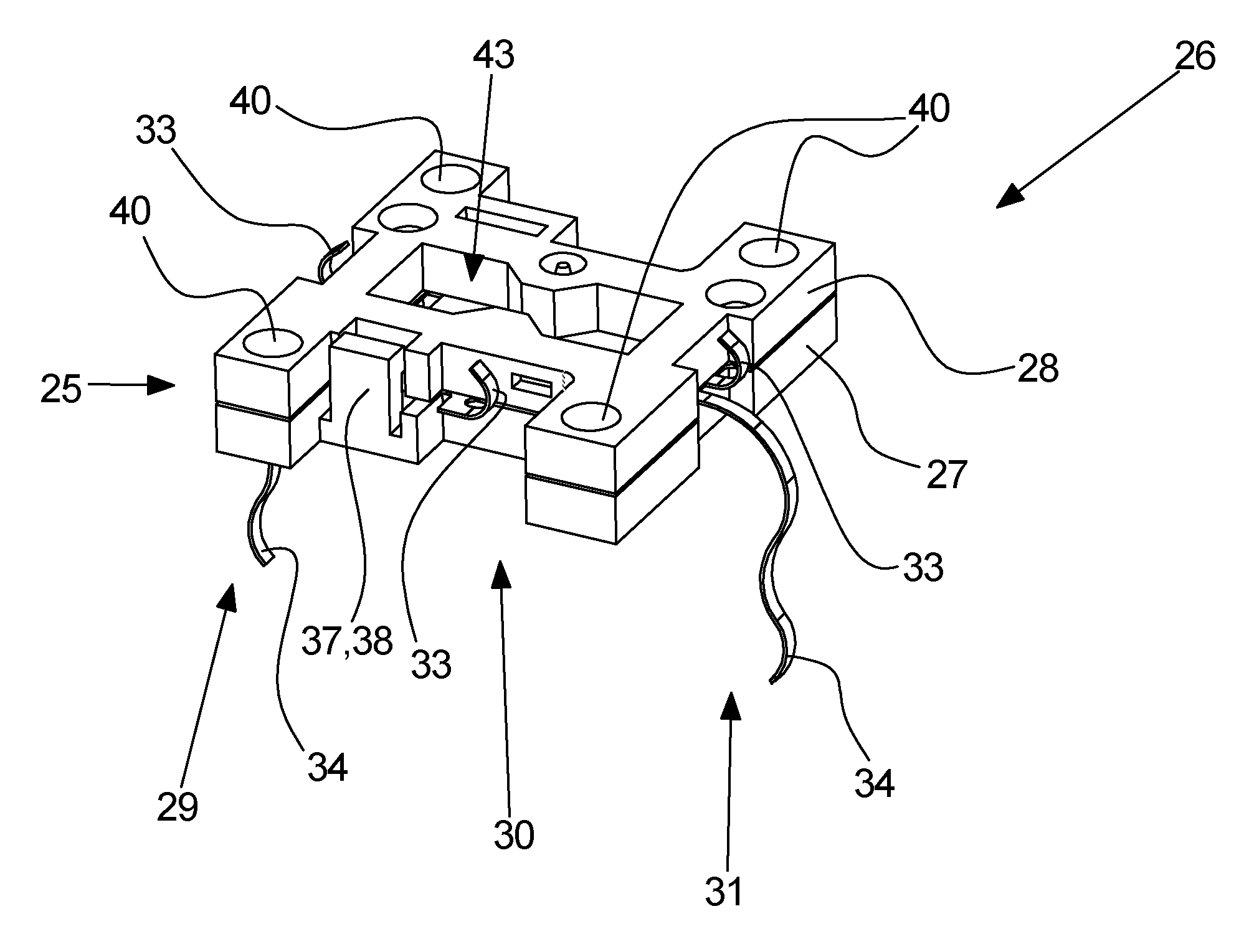
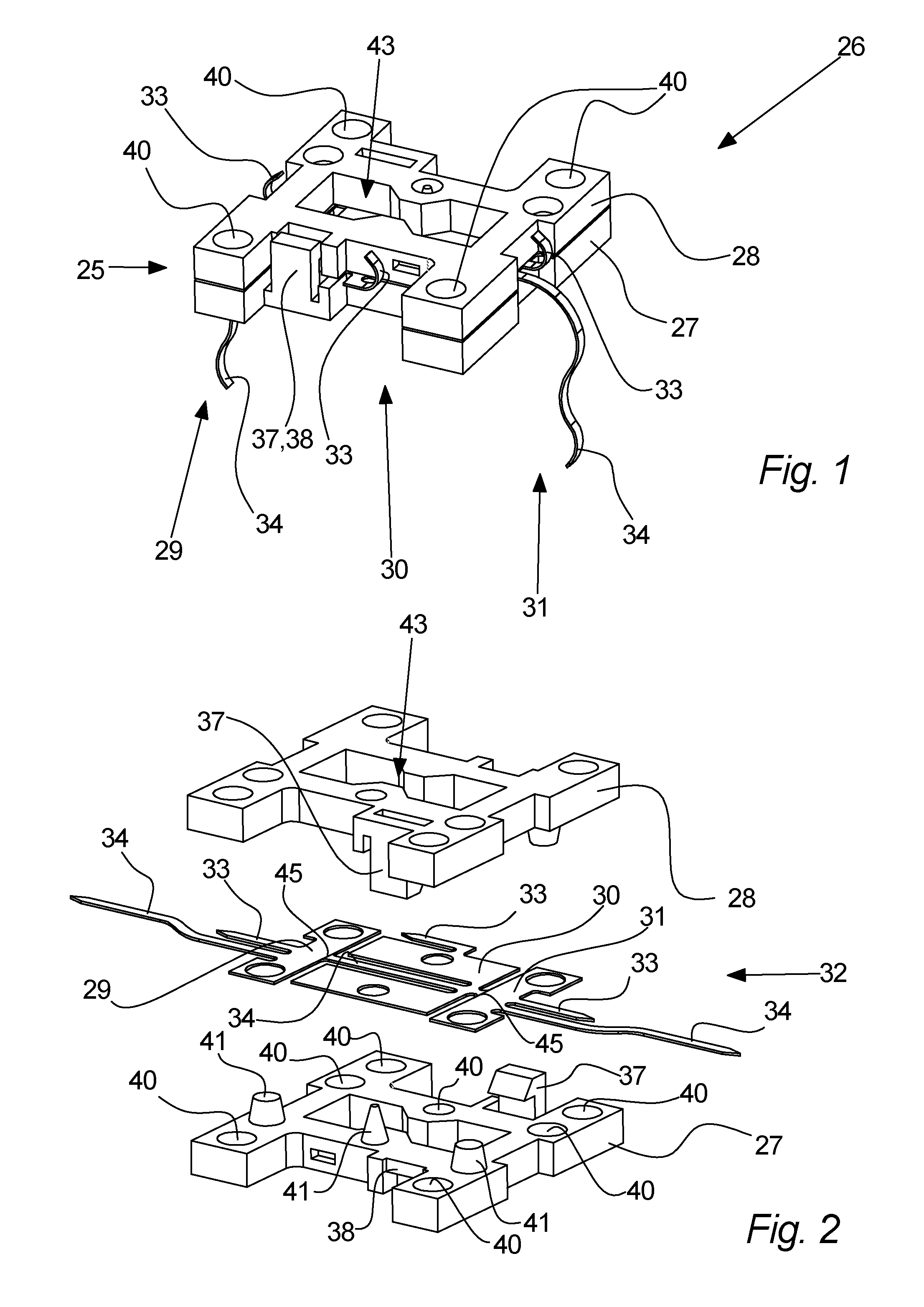
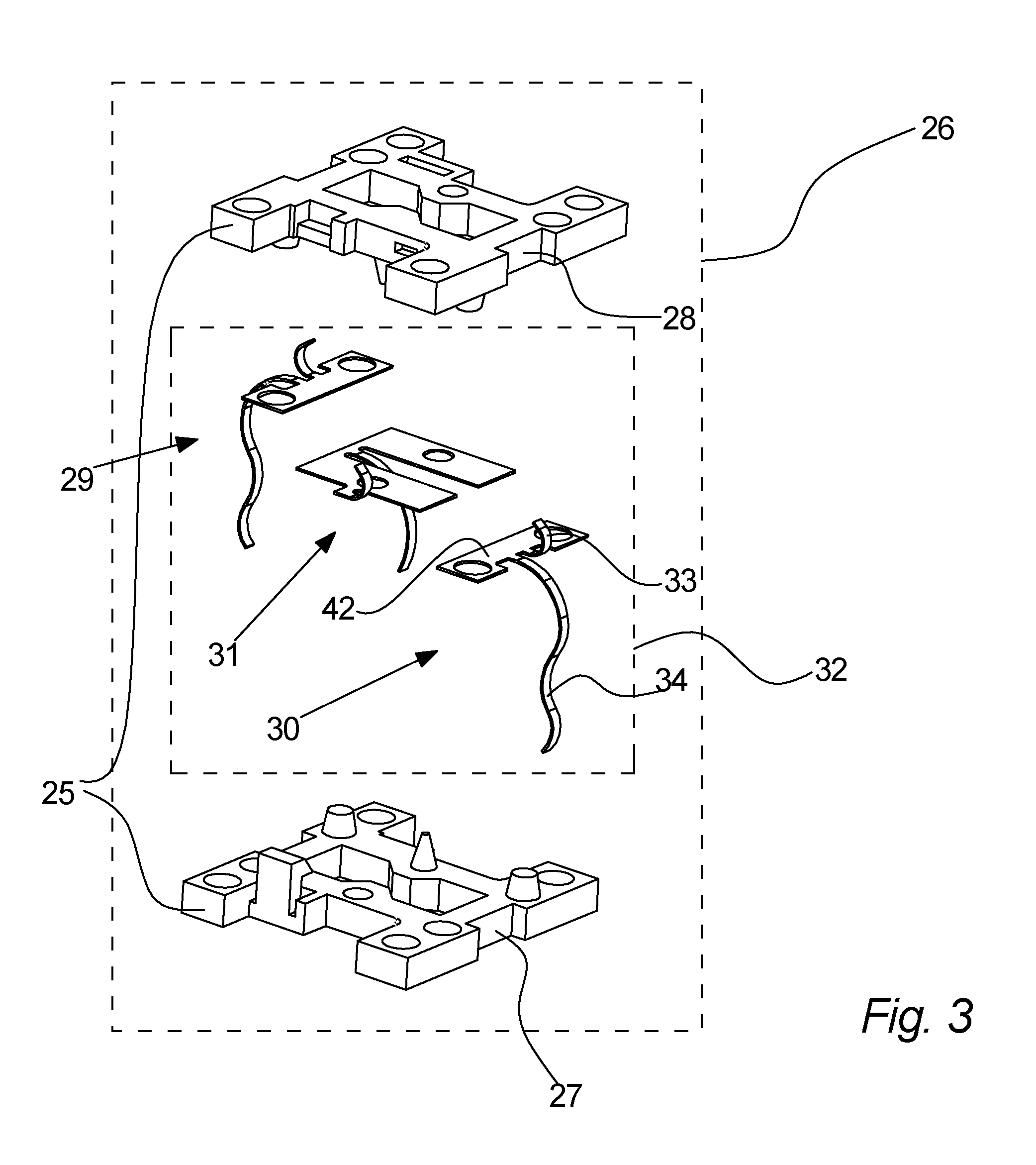
[0226]Referring to FIG. 1, a connection arrangement 26 according to an embodiment of the invention is illustrated. The connection arrangement 26 comprises a set 32 of elastic connectors 29, 30, 31, namely a first connector 29, a second connector 30, and a third connector 31. Each connector comprises a first spring part 33 and a second spring part 34. The set 32 is fixated by an insulating support arrangement 25 made up by a first and a second insulating part 27, 28. Said insulating parts 27, 28 each comprise a latch 37 and a notch 38. The latch 37 on each insulating part 27, 28 is engaging the notch 38 on the opposite insulating part 27, 28, thereby fixating the two insulating parts 27, 28 to each other, and, furthermore, fixating each of the connectors 29, 30, 31. The connectors 29, 30, 31 are thereby kept fixated in a single connection arrangement 26, but kept electrically separated and insulated from each other. It is thereby possible to bring an electronic control arrangement 4 ...


PUM

PropertyMeasurementUnit
ultrasonic flow meteraaaaaaaaaa
electrically insulatingaaaaaaaaaa
electrical separationaaaaaaaaaa

Abstract

An ultrasonic flow meter is disclosed. The ultrasonic flow meter includes a meter housing, a first ultrasound transducer, a second ultrasound transducer, an electronic control arrangement for operating the ultrasonic flow meter, and a connection arrangement being arranged between the electronic control arrangement and the ultrasound transducers. The connection arrangement includes an electrically insulating support arrangement, and a set of elastic connectors for electrically connecting the electronic control arrangement with the first and second ultrasound transducers. The insulating support arrangement mechanically fixat the set of elastic connectors and maintains electrical separation between the set of elastic connectors. Furthermore, a method of assembling an ultrasonic flow meter, a connection arrangement, and a method of manufacturing a connection arrangement are disclosed.

Description

FIELD OF THE INVENTION [0001]The invention relates to an ultrasonic flow meter for measuring the flow of a fluid.BACKGROUND OF THE INVENTION[0002]Several ultrasonic flow meters exists within the prior art.[0003]One example of an ultrasonic flow meter is seen in the international patent application WO 2012 / 113401. According to this prior art, the ultrasonic flow meter comprises two transducers electrically connected to an electronic circuit. One side of each transducer is connected to the electronic circuit, via a spring, while the opposite sides are connected to each other via coupling layers and conductive layers, one of these conductive layers being connected to the electronic circuit by a spring.[0004]There may, however, in some cases exist problems with the solution of the above mentioned prior art in relation to electrically connecting ultrasound transducers with an electric circuit.SUMMARY OF THE INVENTION[0005]It may be an object of the invention to provide a compact ultrason...

Claims


Application Information

Patent Timeline
Patent Type & Authority Applications(United States)
IPC IPC(8): G01F1/66
CPCG01F1/662H04R31/006G01F1/667Y10T29/49005Y10T29/49169Y10T29/49217
Inventor DRACHMANN, JENS
Owner APATOR MIITORS APS
Why Eureka
Try Eureka