

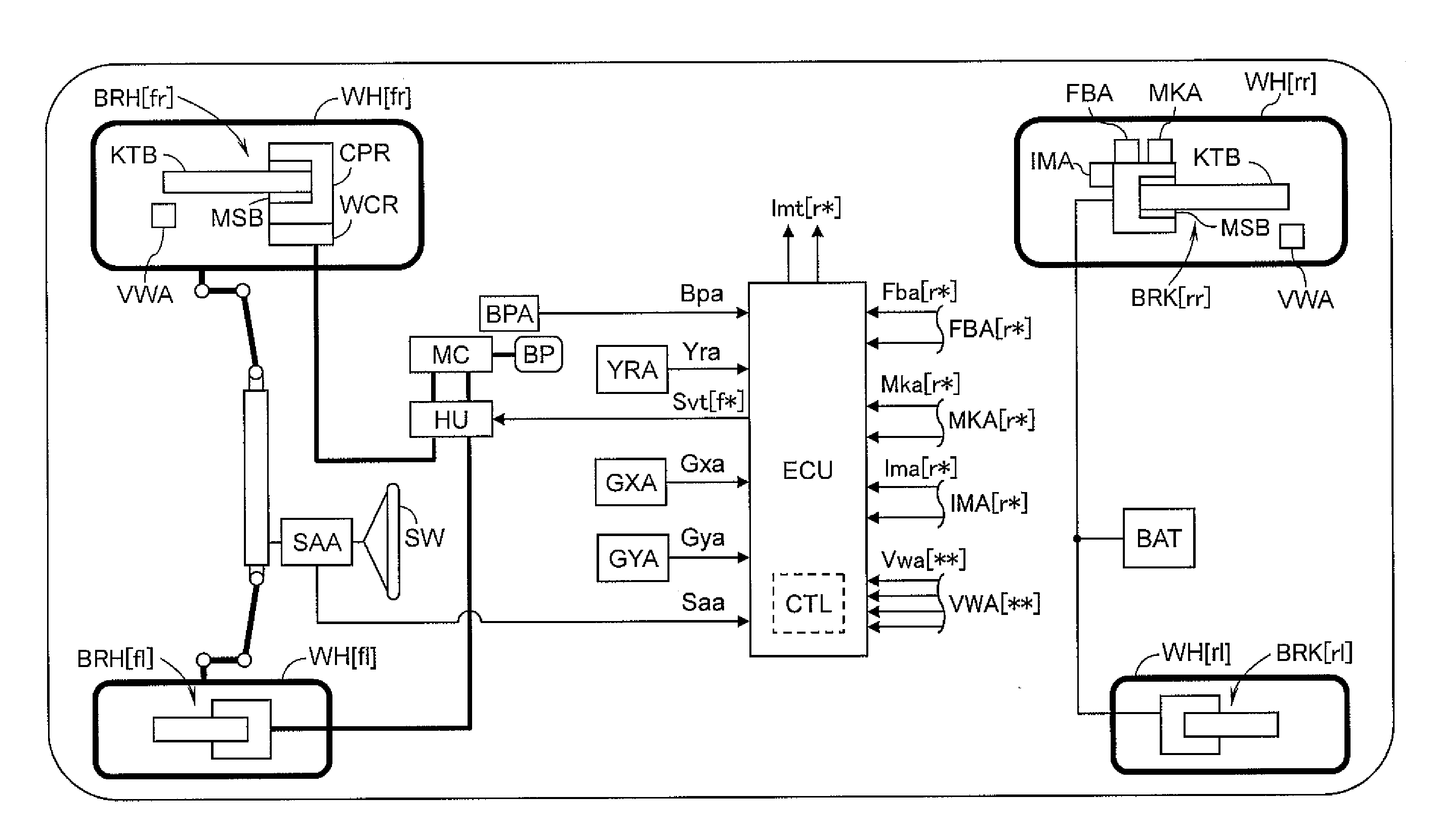
Braking control device for vehicle
a technology for brake control and vehicles, applied in brake systems, process and machine control, instruments, etc., can solve the problems of reducing the maximum speed of electric motors, braking torque, and braking torque, and reducing the gradient (temporal change) of fba
- Summary
- Abstract
- Description
- Claims
- Application Information
AI Technical Summary
Benefits of technology
Problems solved by technology
Method used
Image

Examples
second embodiment
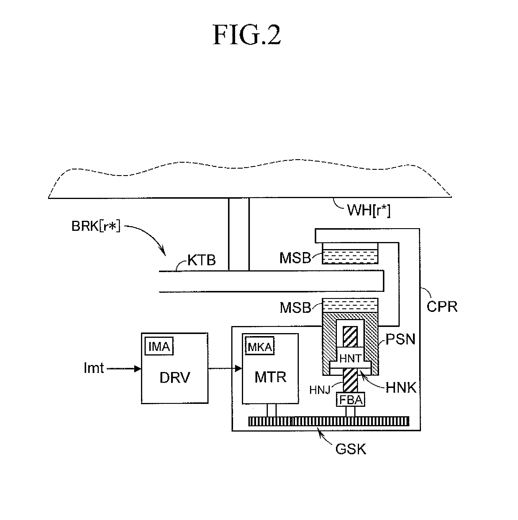
[0086]Next, with reference to FIG. 7, an inertia compensation control block INR according to the present invention is described. In the inertia compensation control block INR, the inertia compensation control for improving responsiveness and convergence of the pressing force ascribable to an inertia of the MTR and the like (inertia of the entire BRK including the inertia of the MTR) is executed. The inertia compensation control block INR includes a control necessity determination calculation block FLG for determining the need of the inertia compensation control, an inertia compensation energization amount calculation block IJK for calculating the target energization amount of the inertia compensation control, and a selection calculation block SNT.
[0087]In the control necessity determination calculation block FLG, whether or not the execution of the inertia compensation control is necessary is determined. The control necessity determination calculation block FLG includes an accelerat...
first embodiment
[0183]In the inertia compensation control block INR of the first embodiment as illustrated in FIG. 6, the Mkt is calculated based on the Fbu, and the Ijt and the Ikt are determined finally. For the same reason as the description of the “pressing force corresponding value Fbs” described above, a correlation exists between the state quantity relating to the “force” of the movable member located in the power transmission path from the output from the MTR to the pressing force of the MSB and the state quantity relating to the “position” thereof. For example, the Fbu and the Mkt may be calculated based on the CHmk in consideration of the correlation. Therefore, in place of the Mkt, a value Fsf obtained by subjecting the target value (target pressing force corresponding value) Fst of the Fbs to delay processing may be second-order differentiated, and the Ijt and the Ikt may be calculated based on a second-order differential value ddFsf.
[0184]In the same manner, in the INR of the second em...
PUM
 Abstract
Description
Claims
Application Information