
Watercraft Fin Plug Assembly

a technology for fin plugs and watercraft, which is applied in the field of watercraft, can solve the problems of insufficient foam of the core, insufficient laminate contact surface of the fin plug, and inability to provide any real support for the fin plug in resisting torsional loads, etc., and achieves the effect of simple shape and convenient installation

Active Publication Date: 2015-08-13
MAIR DESIGNS
View PDF2 Cites 1 Cited by
  • Summary
  • Abstract
  • Description
  • Claims
  • Application Information

AI Technical Summary

Benefits of technology

The patent describes a fin plug assembly for watercraft that has a concave collar shape with raised perimeter rims to resist torsional deformation. The assembly also includes a finishing insert that provides further torsional resistance. The interstitial webs and apertures in the collar provide additional relief formations for bonding the fin plug to the watercraft. The surfaces of the interstitial webs may be grooved and in a preferred embodiment, the web edges are rebated for better surface relief. The shelf-like support may have a central aperture with a complex shape to complement the fin plug shape.

Problems solved by technology

One of the problems encountered with known fin plugs arises from the characteristics of surfboard construction.
In typical installations, the outer laminate of the surfboard is extended partially over the fin plug, but given the size limitations imposed by the locations where the fin plugs are installed on the surfboard, the laminate contact surface offered by the fin plug is generally insufficient to provide any real support to the fin plug in resisting the torsional loads imposed on the fin plug.
However, the low-density foam of the core generally does not have sufficient strength to resist the torsional fin plug loads without deformation or weakening of the surrounding foam over time, with consequential reduction in performance of the fin, cracking and shattering of the laminate in the vicinity of the fin plug and eventually delamination of the laminate from the core.
These fin plugs are typically of injection mouldable plastics, which generally does not bond well to the polyester resin most commonly used to laminate modern watercraft, unless the fin plug is treated, for instance by sanding, to provide some form of mechanical key and even this does little to improve bonding of the plastic to the resin.
In addition, it will be appreciated that this introduces a secondary process that increases the cost and complexity of fin system installation.

Method used


Image

  • Watercraft Fin Plug Assembly
  • Watercraft Fin Plug Assembly
  • Watercraft Fin Plug Assembly

Examples


Embodiment Construction

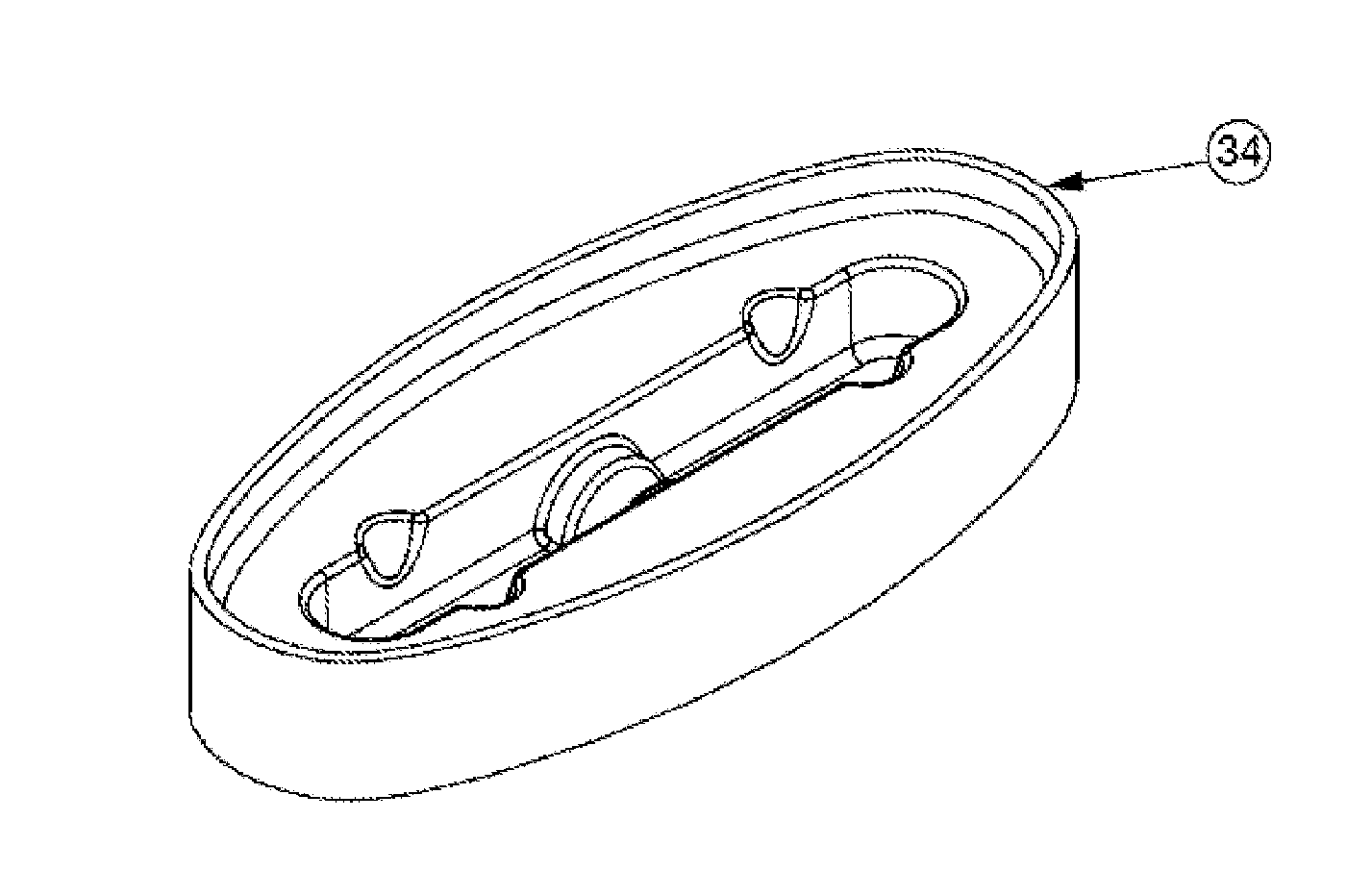
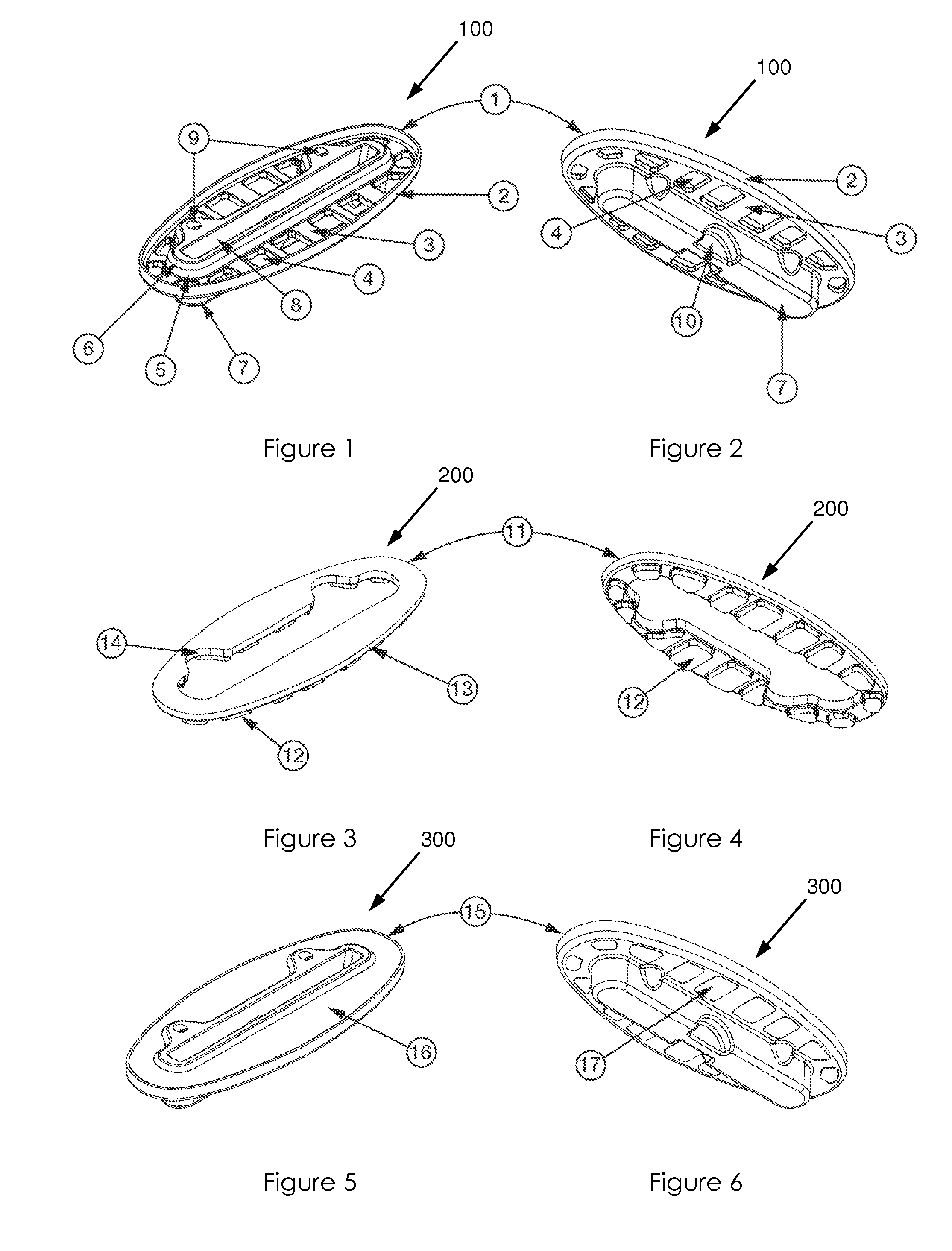
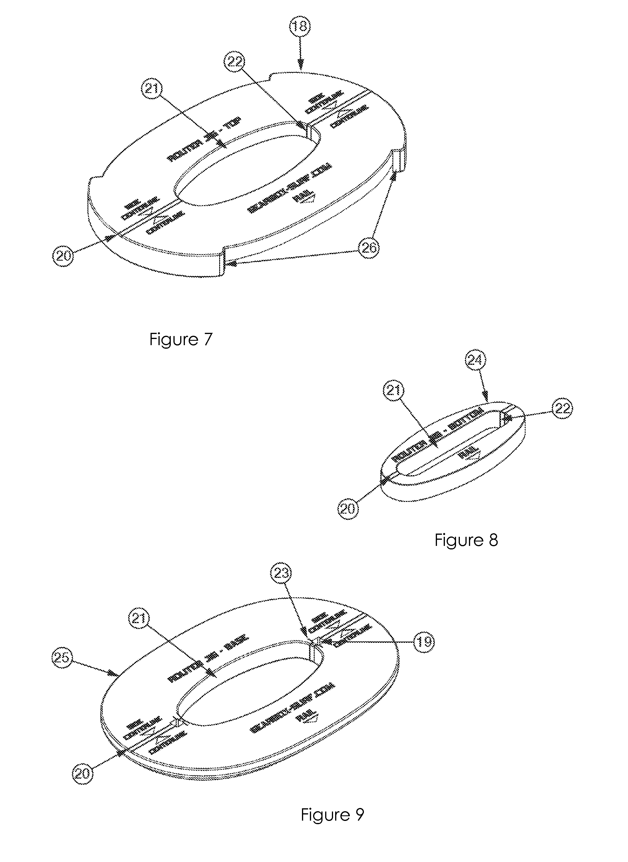
[0056]The fin plug assembly 300 of the invention comprises a number of parts that together constitute a fin mounting device similar to so-called collared or flange-type fin plugs for removably mounting a removable watercraft fin (not shown) on a watercraft. The parts include a fin plug 100 and foam filler or finishing insert 200 that is configured to fit within the fin plug 100. The entire assembly 300 is intended for installation, with or without a foam shelf-like support 31, 32 in a complementally shaped cavity formed in the foam core of a watercraft, such as a surfboard (not shown in full in the drawings).

[0057]The fin plug 100 is integrally moulded from injection moulded plastics with a flange-like perimeter or collar 1 extending about a fin receiving housing or fin box extending about the open end of a fin box constituted by a fin slot 8 and fin box base 7.

[0058]The load beam collar 1 has a rim or lip 2 extending about the perimeter of the load beam collar 1. The raised perimet...


PUM


Abstract

The present disclosure describes a fin plug assembly for removably mounting a watercraft fin on a watercraft. In some embodiments the fin plug assembly includes a fin plug, a fin plug finishing insert and in some instances, a shelf-like support that is configured to house the fin plug assembly. Methods of making, methods of installing, and tools for installing the fin plug assembly in a watercraft are also described.

Description

FIELD OF THE INVENTION[0001]This invention relates to watercraft and in particular to assemblies for removably securing fins to the watercraft.BACKGROUND TO THE INVENTION[0002]A number of watercraft make use of fins that project from the water-facing surface of the craft. On planing craft, such as surfboards, the fins are typically foil-shaped to enhance the directional stability of the craft during high speed planing motion and to facilitate turning.[0003]On watercraft such as surfboards the use of removable fins has become quite commonplace. These fins are removably and interchangeably fitted to the watercraft by means of fin mounting systems embedded in the water-facing surface of the craft, the fin mountings typically having a cavity that is configured to receive the base of the fin. Various securement mechanisms are used to secure the fin base in the mounting system cavity.[0004]In conventional surfboard manufacturing terminology, the fin mounting systems are referred to as fin...

Claims


Application Information

Patent Timeline
IPC IPC(8): B63B35/79
CPCB63B35/793B63B32/66Y10T29/49
Inventor MAIR, ROBIN THOMAS
Owner MAIR DESIGNS
Learn More