Eureka AIR delivers breakthrough ideas for toughest innovation challenges, trusted by R&D personnel around the world.

Engine electrical load shed control

Active Publication Date: 2015-08-13
SIKORSKY AIRCRAFT
View PDF1 Cites 10 Cited by
  • Summary
  • Abstract
  • Description
  • Claims
  • Application Information

AI Technical Summary

Benefits of technology

The invention relates to a method and system for controlling the electrical load shed of an engine. The method involves receiving an accessory load indicator, detecting a request for acceleration of the engine, and depowering one or more electrical buses if the accessory load indicator exceeds a shedding threshold and the engine is being accelerated. The system includes a processor and memory with instructions stored thereon that causes the engine control system to receive an accessory load indicator, detect a request for acceleration of the engine, and depower one or more electrical buses if the accessory load indicator exceeds a shedding threshold and the engine is being accelerated. The technical effects of this invention include reducing the fuel consumption of the engine, improving engine efficiency, and controlling the electrical load shed for the engine based on its current needs.

Problems solved by technology

Engine acceleration and resultant aircraft handling qualities are often compromised by a requirement to remain below the engine manufacturer's peak loading specifications for such items as an engine-driven direct current (DC) starter / generator (also referred to simply as a “generator”) which is geared to an accessory gearbox (AGB) of the engine.
Accessory loads on the AGB compete against the ability to quickly accelerate the engine to develop power.
There is a tradeoff between the maximum DC generator loads that can be accommodated by the engine versus an acceleration schedule of the engine.
Excessive loads on the AGB consume engine surge margin and, if poorly managed, can lead to engine compressor stall and loss of engine power.
In a rotorcraft, slow engine acceleration can lead to poor rotor speed management, which diminishes handling with excessive yaw disturbances and an inability to arrest descent quickly.
Further, turbine helicopter engines are limited in the amount of power that can be extracted from the AGB as driven by the engine compressor (Ng).
If the electrical load is not limited, it could cause an engine surge.
This has an undesirable result of limiting system electrical capacity and limiting aircraft maneuvering performance, i.e., handling qualities.

Method used


Image

  • Engine electrical load shed control
  • Engine electrical load shed control
  • Engine electrical load shed control

Examples


Embodiment Construction

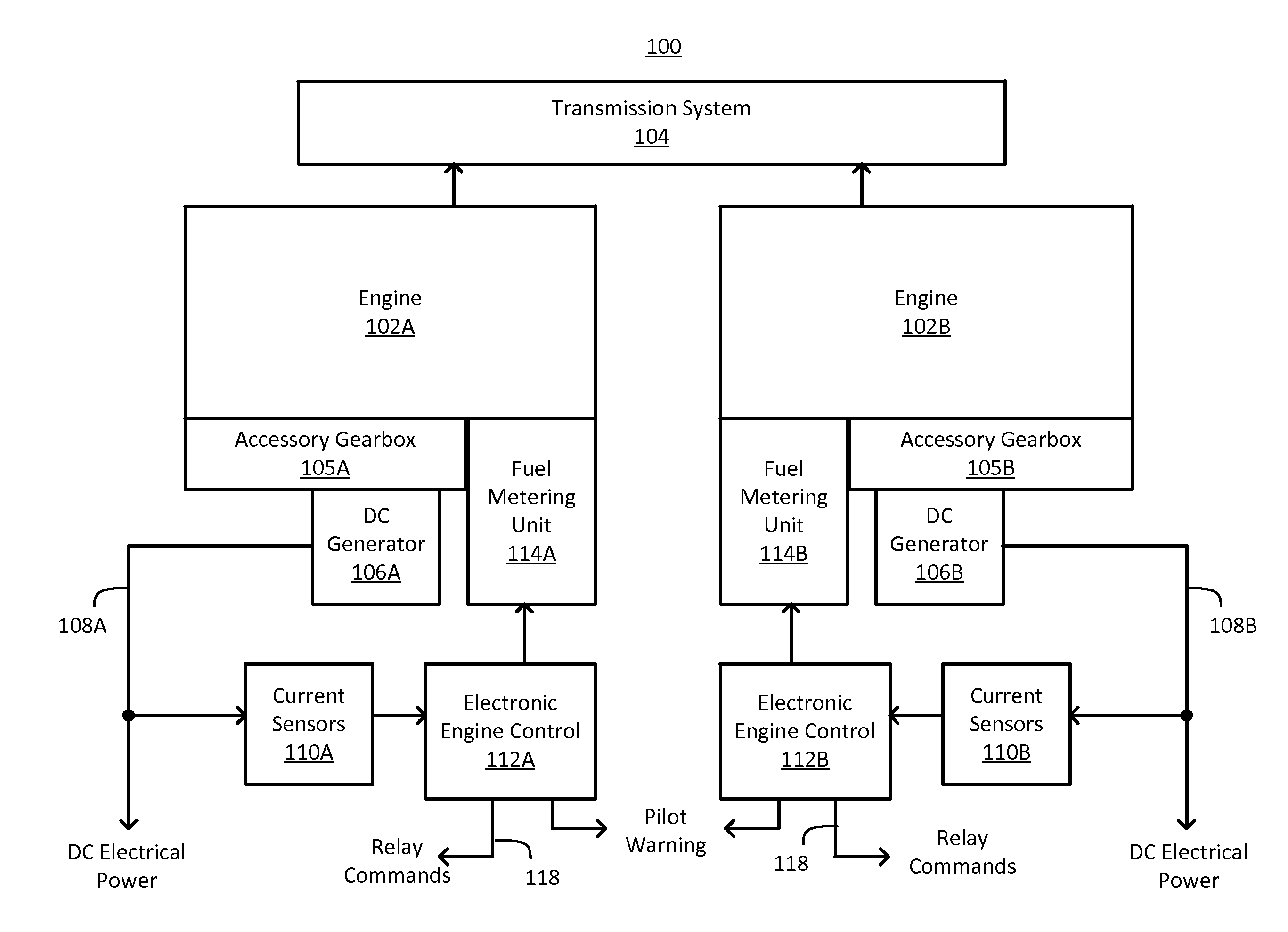
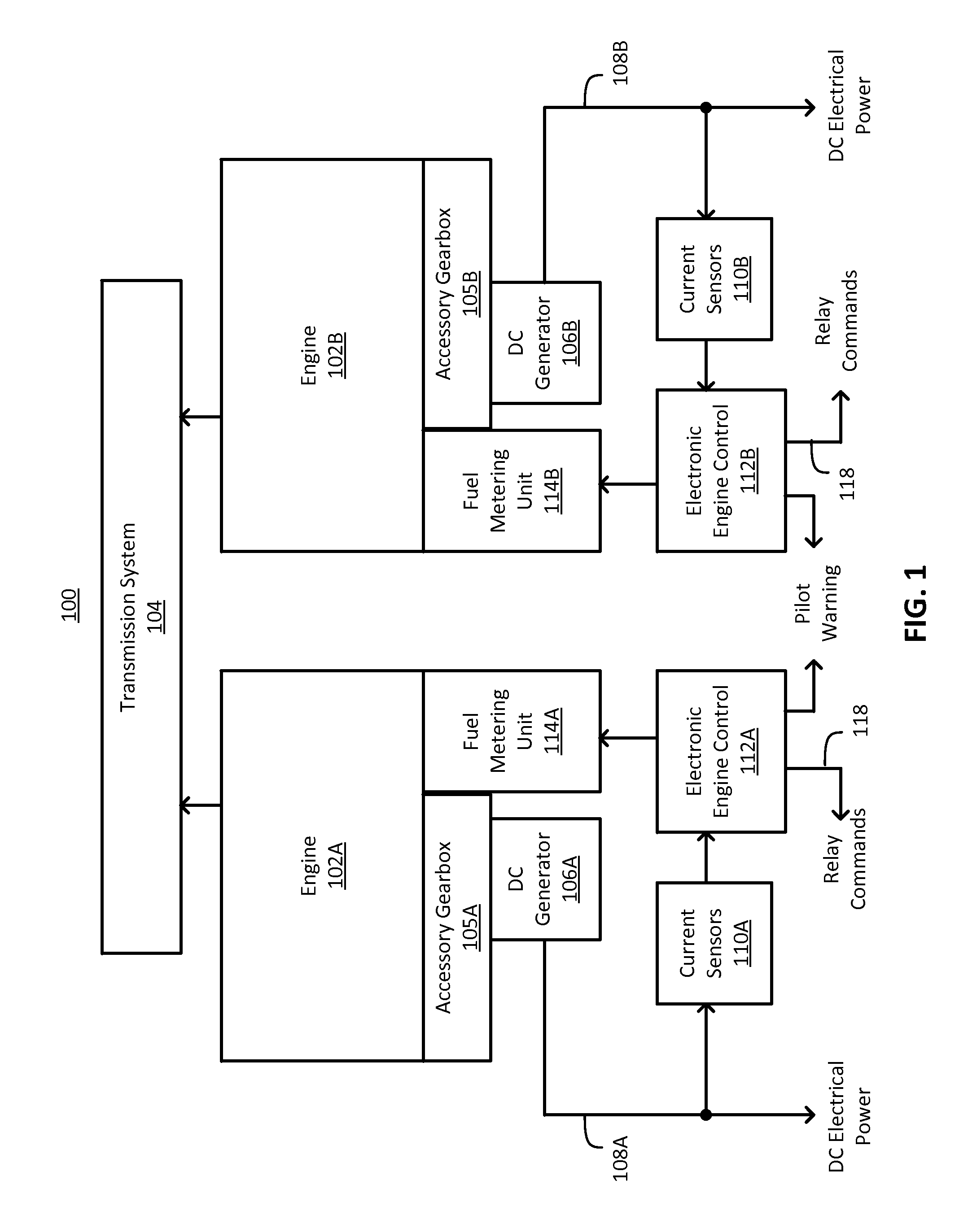
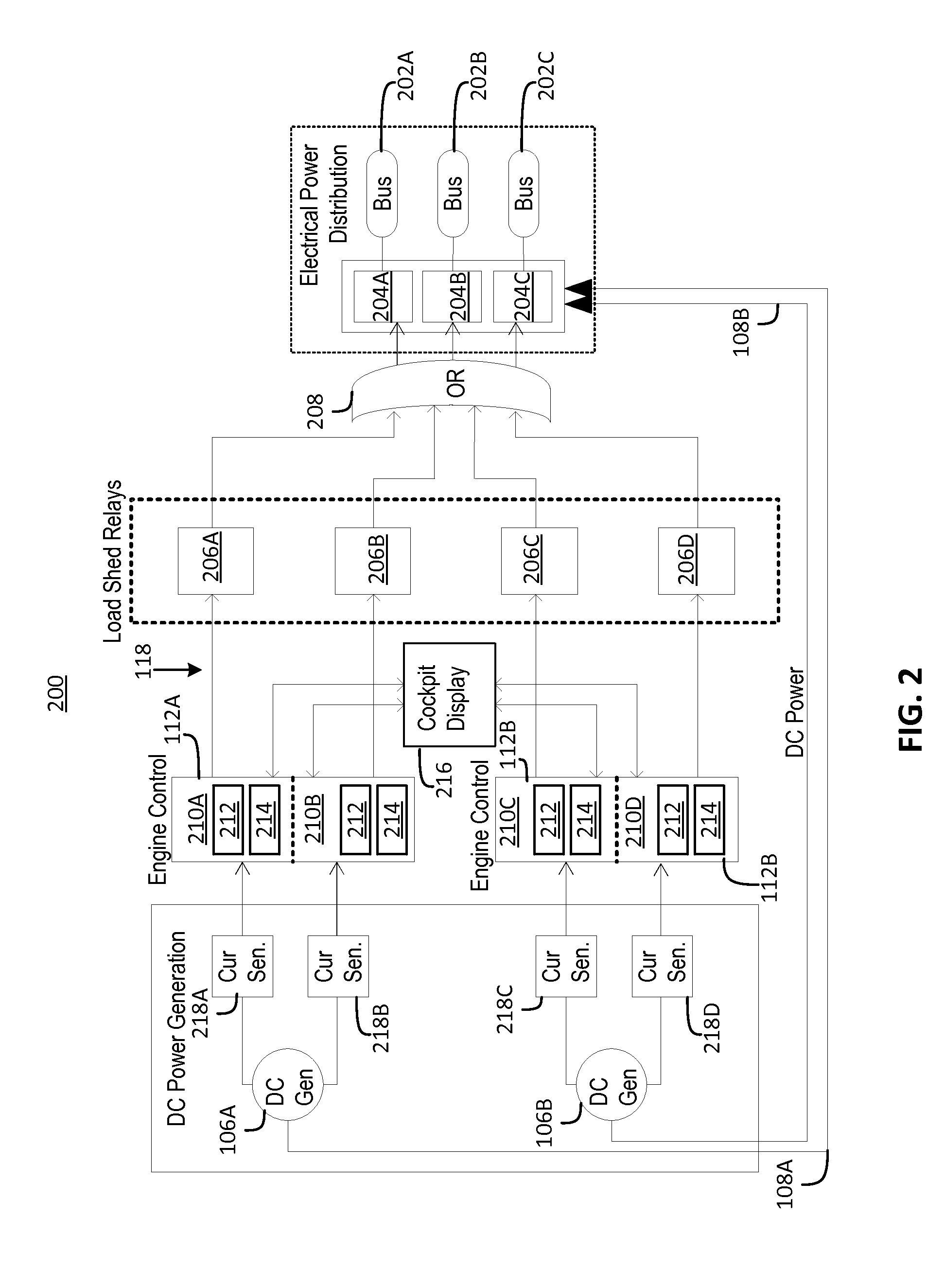
[0020]In embodiments, an engine control system for an aircraft, such as a rotorcraft, monitors loads on each engine and sheds electrical loads under predetermined conditions. The engine control system is configured to automatically manage non-essential electrical loads based on aircraft operating conditions. A full authority digital engine control (FADEC), i.e., an electronic engine control, can be utilized to directly monitor DC electrical loads and to directly command a shedding / reduction of non-essential DC electrical loads when engine operating conditions demand. Generator load (amperage) is measured by aircraft current sensors as an analog signal which is used as an input to the FADEC for each engine. Each FADEC typically includes at least two separate processing systems, referred to as “channels”. Dedicated sensors, one-each per FADEC channel, provide for crosscheck fault detection and redundancy. FADEC hardwired outputs are employed to directly and redundantly activate aircra...


PUM


Abstract

A method of engine electrical load shed control includes receiving an accessory load indicator corresponding to an accessory load of an engine. A request for acceleration of the engine is detected. One or more electrical buses are depowered based on the accessory load indicator exceeding a shedding threshold and detection of the request for acceleration of the engine.

Description

CROSS-REFERENCE TO RELATED APPLICATIONS[0001]This application claims the benefit of U.S. provisional patent application Ser. No. 61 / 938,383 filed Feb. 11, 2014, the entire contents of which are incorporated herein by reference.BACKGROUND OF THE INVENTION[0002]The subject matter disclosed herein generally relates to engine control systems, and more particularly to engine electrical load shed control.[0003]Engine acceleration and resultant aircraft handling qualities are often compromised by a requirement to remain below the engine manufacturer's peak loading specifications for such items as an engine-driven direct current (DC) starter / generator (also referred to simply as a “generator”) which is geared to an accessory gearbox (AGB) of the engine. Accessory loads on the AGB compete against the ability to quickly accelerate the engine to develop power. Accessory loads can include pumps, generators, and the like. There is a tradeoff between the maximum DC generator loads that can be acc...

Claims


Application Information

Patent Timeline
IPC IPC(8): B64D31/06B64D45/00B64D43/00
CPCB64D31/06B64D45/00B64D43/00B60R16/03B64D2221/00F02D29/02F02D41/021F02D41/10F02D41/1497F02D2250/18F02D2250/22
Inventor JUDGE, JOHN H.KEFALAS, NICHOLAS D.EISENHAUER, MARK P.BOURNE, FREDERICK L.ANDREJCZYK, ROBERT J.WADE, MICHAEL PATRICK
Owner SIKORSKY AIRCRAFT
Why Eureka
Eureka Blog
Learn More