Hybrid Pump Control for Multi Fuel Engine System

a multi-fuel engine and hybrid technology, applied in the direction of electric generator control, electric control, machines/engines, etc., can solve the problems of limited fuel supply and similar inefficient machine operation

Active Publication Date: 2015-08-13
CATERPILLAR INC
View PDF3 Cites 101 Cited by
  • Summary
  • Abstract
  • Description
  • Claims
  • Application Information

AI Technical Summary

Benefits of technology

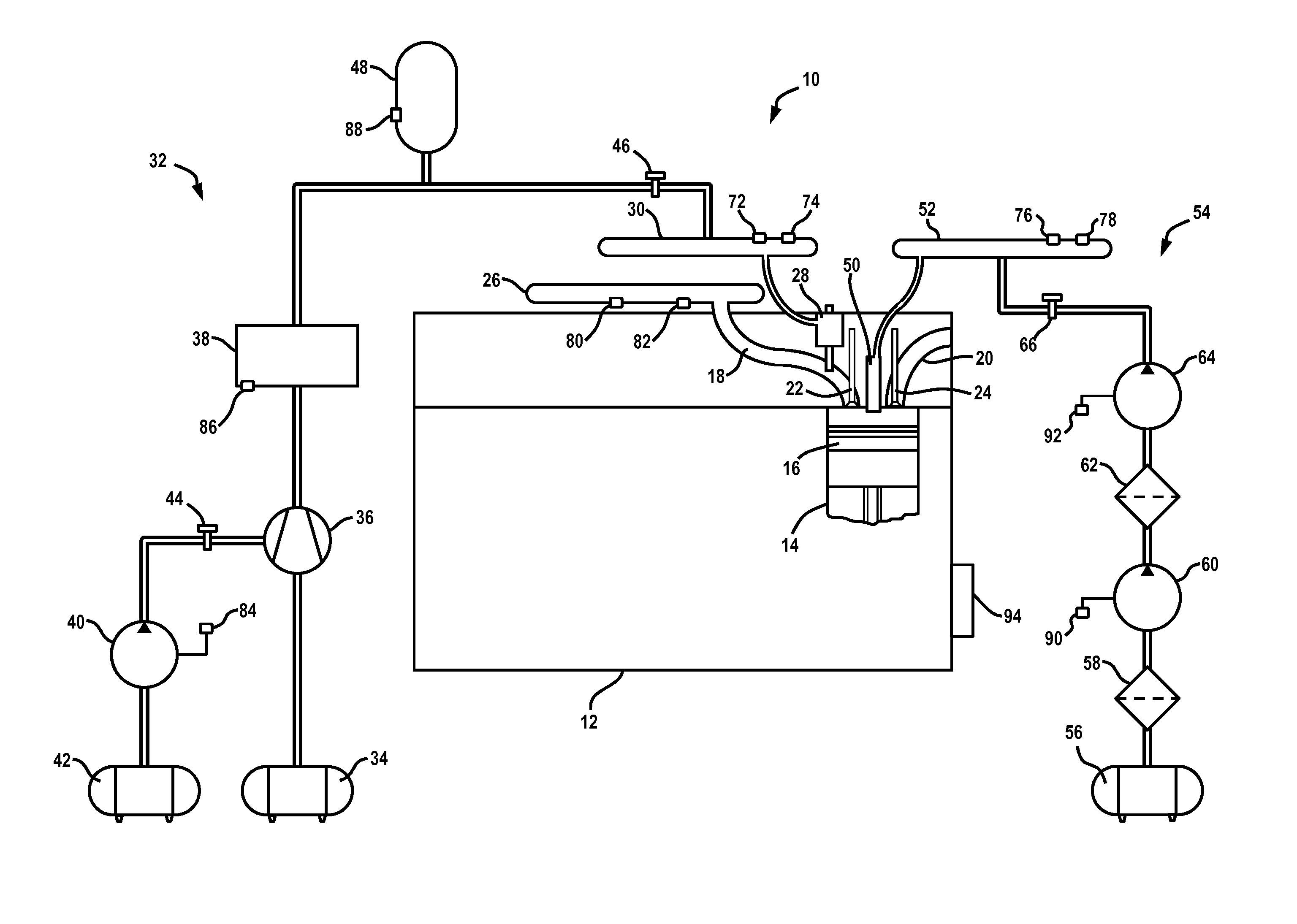
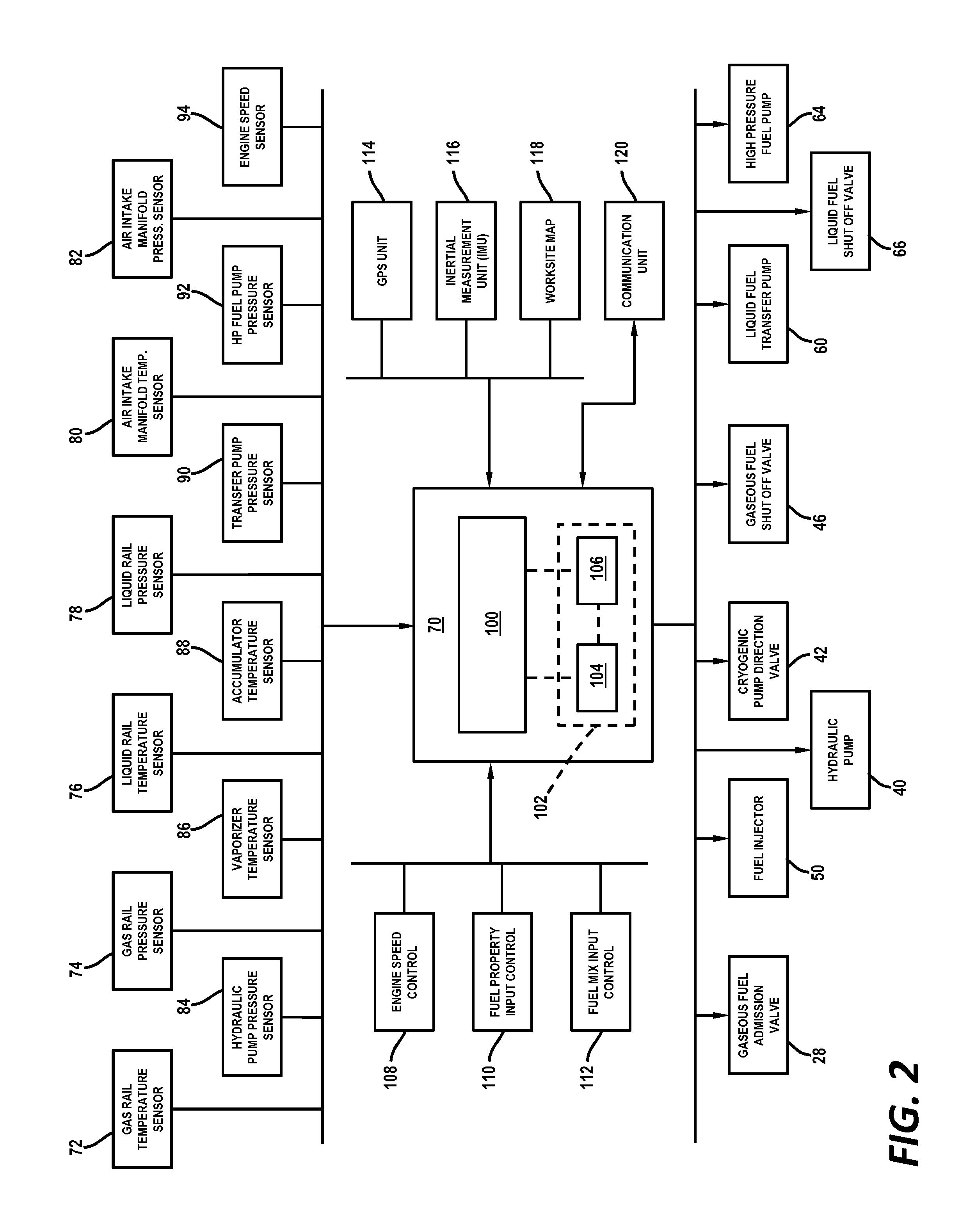
[0005]In one aspect of the present disclosure, an engine system for a machine is disclosed. The engine system may include an engine, a fuel supply system and energy accumulator and an electronic control module operatively connected to the engine, the fuel supply system and the energy accumulator. The fuel supply system may include a fuel reservoir in fluid communication with the engine, and a pump operatively connected to the fuel reservoir to produce flow of fuel from the fuel reservoir to the engine. The energy accumulator may be operatively connected to the fuel supply system, and the energy accumulator may have capacity to store energy and be configured to discharge the energy to produce a fuel flow in the fuel supply system. The electronic control module may be configured to determine whether the energy accumulator is charged with a charged energy amount that is greater than a recharge limit amount, to determine a machine operational state for the machine in response to determining that the charged energy amount is less than the recharge limit amount, and to execute an energy accumulator charging operation to increase the charged energy amount in the energy accumulator in response to determining that the machine operational state is equal to an energy accumulator charging state.

Problems solved by technology

In combat settings, for example, enemy action or unit isolation may limit the available fuel supply and personnel may need to resort the type of fuel available for usage from enemy and civilian sources.
Where the hydraulic pump is electric and powered by the battery pack, the hydraulic pump may run off the battery pack for a time, but eventually the batteries must be recharged by the engine, and possibly while the engine is propelling the machine, and thereby resulting in similar inefficient operation of the machine.

Method used


Image

  • Hybrid Pump Control for Multi Fuel Engine System
  • Hybrid Pump Control for Multi Fuel Engine System
  • Hybrid Pump Control for Multi Fuel Engine System

Examples


Embodiment Construction

[0014]Although the following text sets forth a detailed description of numerous different embodiments of the present disclosure, it should be understood that the legal scope of protection is defined by the words of the claims set forth at the end of this patent. The detailed description is to be construed as exemplary only and does not describe every possible embodiment since describing every possible embodiment would be impractical, if not impossible. Numerous alternative embodiments could be implemented, using either current technology or technology developed after the filing date of this patent, which would still fall within the scope of the claims defining the scope of protection.

[0015]It should also be understood that, unless a term is expressly defined in this patent using the sentence “As used herein, the term ‘______’ is hereby defined to mean . . . ” or a similar sentence, there is no intent to limit the meaning of that term, either expressly or by implication, beyond its p...


PUM


Abstract

In an engine system of a machine having a multi fuel engine system, an energy accumulator is provide to accumulate and store energy when the engine system is in a low engine power usage or low engine load state, and to discharge energy from the energy accumulator when the engine system is in a high engine usage or high engine load state. The energy accumulator may be implemented, for example, in the form of a gaseous fuel accumulator that delivers gaseous fuel to the engine, a hydraulic fuel accumulator that provides pressurized fluid to power a fuel pump, or a battery pack that powers an electric hydraulic pump.

Description

TECHNICAL FIELD[0001]The present disclosure relates generally to multi fuel engines capable of operating with liquid fuel, with gaseous fuel and with a mixture of liquid and gaseous fuels, and more particularly, to methods and systems for controlling cryogenic, hydraulic and pneumatic pumps in multi fuel engines to efficiently store hydraulic, electrical and / or mechanical power for providing power assist during heavy engine loading.BACKGROUND[0002]A multi fuel engine refers generically to any type of engine, boiler, heater or other fuel-burning device which is designed to burn multiple types of fuels in its operation. Multi fuel engines have application in diverse areas to meet particular operational needs in the operating environment. For example, a common use of multi fuel engines is in military vehicles so that vehicles in various deployment locations may run a wide range of alternative fuels such as gasoline, diesel or aviation fuel. In combat settings, for example, enemy action...

Claims


Application Information

Patent Timeline
Patent Type & Authority Applications(United States)
IPC IPC(8): F02D41/00H02J7/34F02M37/08F02M37/00F02D41/04F02M21/02
CPCF02D41/0027F02D41/04F02M21/0224F02M2037/085F02M37/08F02M37/0088H02J7/34F02M21/0245F02D41/0025F02D19/0684F02D19/105F02D41/3082H02J7/007Y02T10/30
Inventor ZHANG, YANCHAIBODDU, MALLIKHARJUNA R.JACOBSON, EVAN E.
Owner CATERPILLAR INC
Why Eureka
Try Eureka