
Laser radar apparatus and method of acquiring image thereof

a laser radar and apparatus technology, applied in the field of laser radar systems, can solve the problems of inability to rapidly and precisely acquire an image of an object within a short distance, increased intensity of the peak of the laser light source, and saturation of the detector

Active Publication Date: 2015-08-13
ELECTRONICS & TELECOMM RES INST
View PDF8 Cites 67 Cited by
  • Summary
  • Abstract
  • Description
  • Claims
  • Application Information

AI Technical Summary

Benefits of technology

The invention is a laser radar system that can create pictures of objects at different distances from the device. It uses a laser efficiently to capture images. The "technical effect" is that the device can capture pictures of objects from close to far away with a single laser.

Problems solved by technology

In this case, the laser radar adjusting an output of the pulse light source adjusts an output of the laser radar when measuring a short distance, so that there is an advantage in that a detector is prevented from being saturated, but has a disadvantage in that it is impossible to rapidly and precisely acquire an image of an object within a short distance.
However, when the pulse width is decreased in the light source unit, there is a disadvantage in that an intensity of the peak of the laser light source may be increased, and the detector may be saturated.
However, when the pulse width is increased, there is a disadvantage in that the peak output of the pulse is decreased, and a signal does not proceed far.

Method used


Image

  • Laser radar apparatus and method of acquiring image thereof
  • Laser radar apparatus and method of acquiring image thereof
  • Laser radar apparatus and method of acquiring image thereof

Examples


Embodiment Construction

[0055]Hereinafter, an embodiment of the present invention will be described with reference to the accompanying drawings in detail. However, the present invention is not limited to an embodiment disclosed below and may be implemented in various forms and the scope of the present invention is not limited to the following embodiments. Rather, the embodiment is provided to more sincerely and fully disclose the present invention and to completely transfer the spirit of the present invention to those skilled in the art to which the present invention pertains, and the scope of the present invention should be understood by the claims of the present invention.

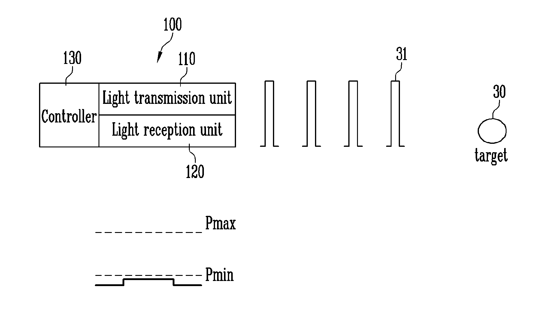
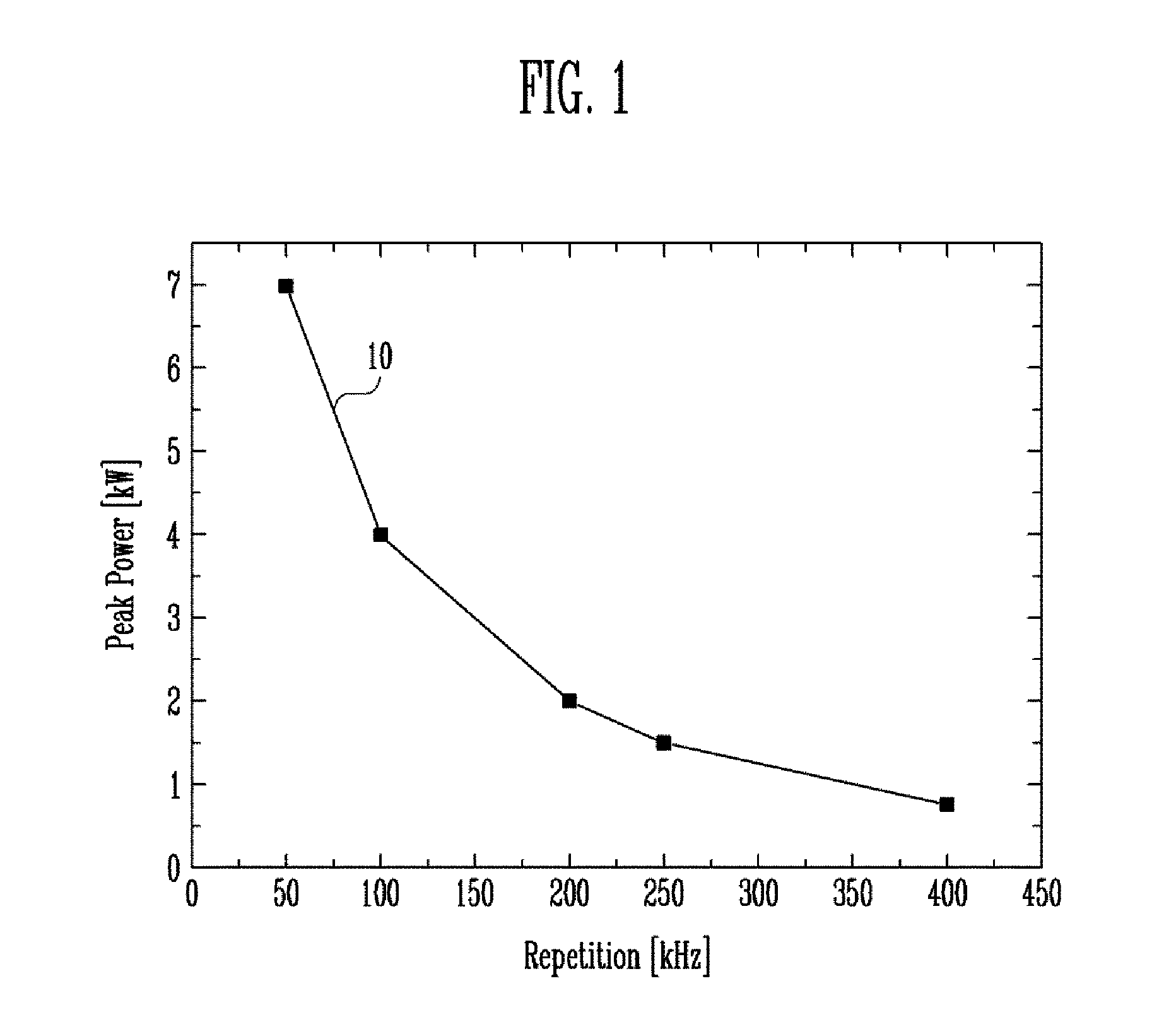
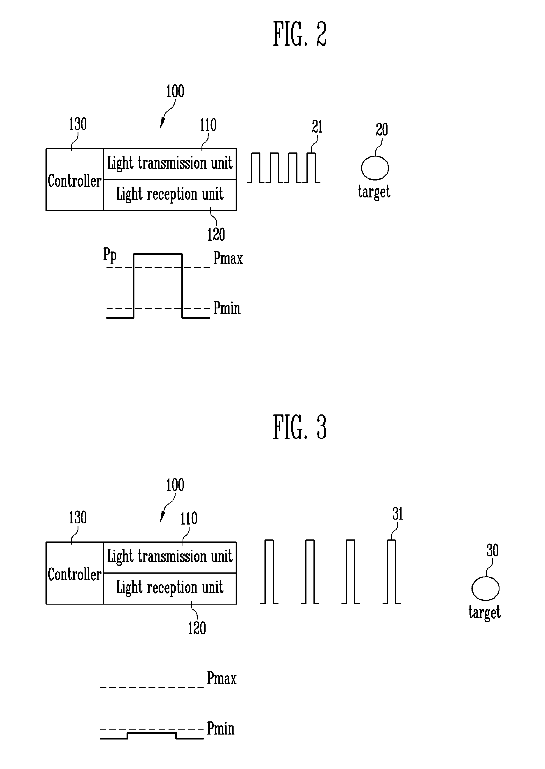
[0056]A laser radar apparatus of the present invention changes a repetition rate of a laser according to a distance by using a characteristic that when the repetition rate of a pulse is increased, an output of a pulse is decreased, and when the repetition rate of a pulse is decreased, an output of a pulse is increased. Accordingly, the ...


PUM


Abstract

Disclosed is a laser radar apparatus. The laser radar apparatus includes: a light transmission unit configured to output a laser pulse by using a light source; a light reception unit configured to receive a reflected laser pulse in connection with the laser pulse; and a controller configured to adjust a repetition rate of the laser pulse of the light source, in which the controller adjusts the repetition rate of the laser pulse based on at least one of reception power, a target distance, a movement speed, a vertical angle, and a radiation angle.

Description

CROSS-REFERENCE TO RELATED APPLICATION[0001]This application is based on and claims priority from Korean Patent Application No. 10-2014-0016065, filed on Feb. 12, 2014, with the Korean Intellectual Property Office, the disclosure of which is incorporated herein in its entirety by reference.BACKGROUND[0002]1. Field[0003]The present invention relates to a laser radar system, and more particularly, to a laser radar apparatus for acquiring an image by using a laser radar light source having a variable pulse repetition rate, and a method of obtaining an image thereof.[0004]2. Discussion of Related Art[0005]A general laser radar system is utilized as an image sensor device for acquiring a 3-dimensional image of an object. The laser radar system is utilized in various fields, such as an industrial robot, a military robot, an autonomous robot, an autonomous vehicle, a structure diagnosis system, and a landslide monitoring system.[0006]The laser radar system adopts a method of outputting lig...

Claims


Application Information

Patent Timeline
IPC IPC(8): G01S17/89G01S7/483G01S17/02G01S17/10
CPCG01S17/89G01S7/483G01S17/02G01S17/10G01S7/484
Inventor SEO, HONG SEOKMHEEN, BONG KIOH, MYOUNG SOOKSIM, JAE SIKSONG, JUNG HOSONG, MIN HYUP
Owner ELECTRONICS & TELECOMM RES INST
Learn More