Vehicular head-up display device

Active Publication Date: 2015-08-13
DENSO CORP
View PDF4 Cites 20 Cited by
  • Summary
  • Abstract
  • Description
  • Claims
  • Application Information

AI Technical Summary

Benefits of technology

[0012]In the above vehicular head-up display device, when the driver changes the request position to a new position in a direction toward the reset position, the reflector adjusts the virtual image position to the request position. Suppose that while the virtual image position is changed to the reset position, the rotation direction of the stepper motor is controlled at the same rotation direction, and that when the ignition switch is turned on next time, the stepper motor is controlled to rotate in an opposite direction in order to move the virtual image position from the reset position to the request position by the reflector. In this case, this reverse operation causes a hysteresis effect and causes misalignment of the virtual image, despite a simple att

Problems solved by technology

Additionally, because this process is performed when the ignition key is turned on, it takes time before a display image is displayed through the windshield.
In this case, this reverse

Method used


Image

  • Vehicular head-up display device
  • Vehicular head-up display device
  • Vehicular head-up display device

Examples


Example

First Embodiment

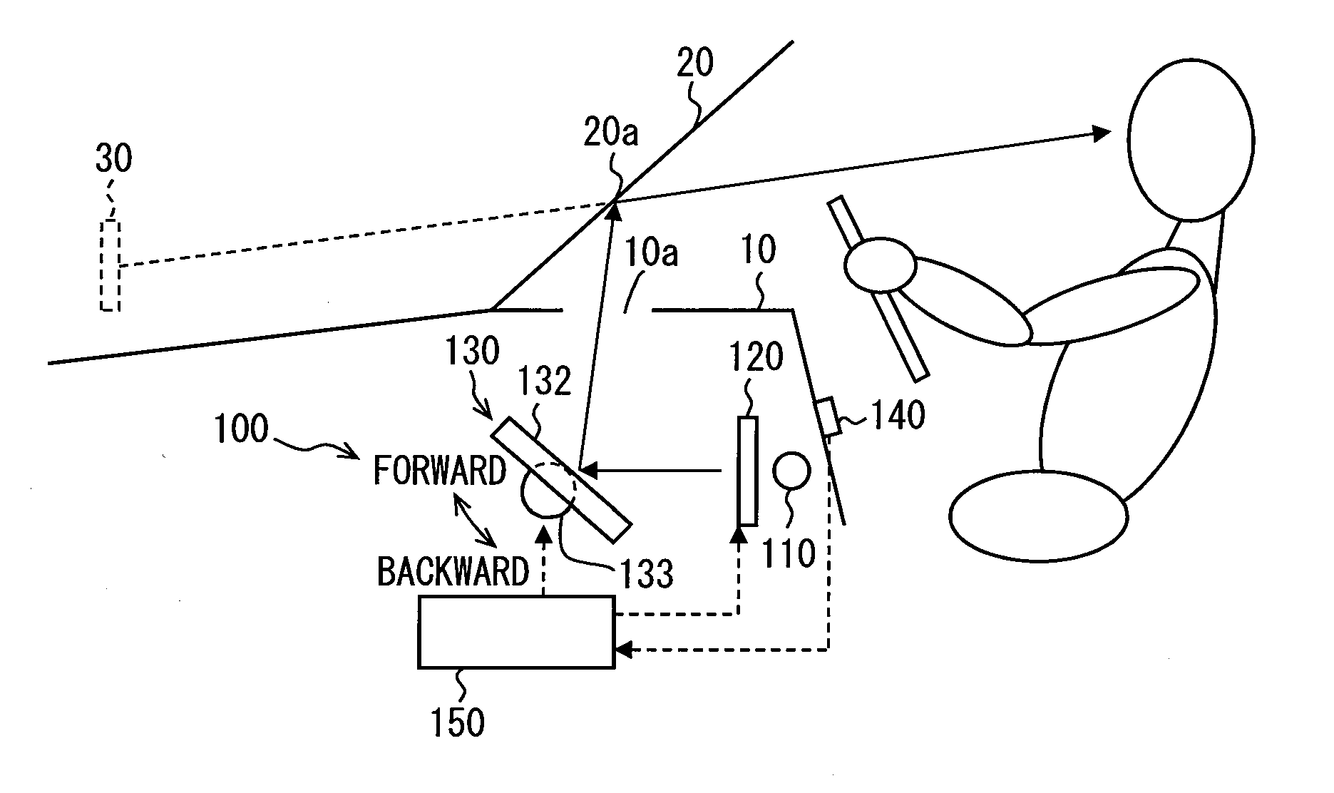
[0030]A vehicular head-up display device 100 according to the first embodiment will be described with reference to FIGS. 1 through 11. As illustrated in FIG. 1, the vehicular head-up display device (Head-Up Display) 100 is applied to vehicles. A liquid crystal display 120 emits display light representing display information. The vehicular head-up display device 100 projects the display light onto a projection position 20a on a vehicle's windshield 20. The vehicular head-up display device 100 forms a display image 30 of the display information, so that the display image 30 appears ahead of the vehicle and on a line that connects a driver with the projection position 20a. The vehicular head-up display device 100 thereby allows the driver to view the display image 30 as a virtual image. Using the vehicular head-up display device 100, the driver can view the display image 30 and the vehicle's foreground overlapped with each other. The vehicular head-up display device 100...

Example

Second Embodiment

[0078]FIGS. 11 through 13 illustrate the HUD 100 (positions of the display image 30 and a flowchart) according to the second embodiment. The second embodiment differs from the first embodiment in the contents of the control performed by the controller 150.

[0079]As illustrated in (1) of FIGS. 11 and (1) of FIG. 12, the reset position according to the second embodiment is predetermined above the driver-specified position and is located to the upper end of the windshield 20. As illustrated in FIG. 11, the display image 30 is moved upward to adjust the driver-specified position so that the driver-specified position is changed in the direction to approach the reset position. In this case, the rotation direction of the stepper motor 133 (mirror portion 132) for the adjustment coincides with the rotation direction of the stepper motor 133 (mirror portion 132) to change the display image 30 from the driver-specified position to the reset position. As illustrated in FIG. 12,...


PUM


Abstract

A vehicular head-up display device is provided. The vehicular head-up display device includes: a reflector for reflecting display light, which is emitted from a display, to a windshield to display a virtual image; a stepper motor for rotating the reflector and a controller for controlling the stepper motor to control a rotation position of the reflector. When a driver changes a request position of the virtual image to a new position in a direction toward a reset position and the ignition switch is turned off, the controller rotates the stepper motor to change the position of the virtual image to the reset position and thereafter instructs the stepper motor to rotate by a specified angle corresponds to a hysteresis generated at a time of a change in the rotation direction of the reflector between a forward rotation direction and backward rotation direction.

Description

CROSS REFERENCE TO RELATED APPLICATION[0001]This application is based on Japanese Patent Application No. 2012-197338 filed on Sep. 7, 2012, the disclosures of which are incorporated herein by reference.TECHNICAL FIELD[0002]The present disclosure relates to a vehicular head-up display device that uses a reflecting mirror to reflect an image displayed on a display onto a projection area of a vehicular windshield and allows a virtual image of the image projected onto the projection area to overlap with the vehicle foreground viewed from an eye point in the vehicle through the windshield.BACKGROUND ART[0003]For example, patent literature 1 describes a conventional vehicular head-up display device. The vehicular head-up display device (vehicular display device) according to patent literature 1 includes a concave mirror, a motor, and a controller. The concave mirror reflects display light, which comes from a projector, onto a vehicle's windshield. The motor rotates the concave mirror in r...

Claims


Application Information

Patent Timeline
IPC IPC(8): G02B27/01B60K35/00
CPCG02B27/0101B60K35/00G02B2027/0154B60K2350/2052B60K2350/2065G02B27/0149G02B27/01G02B2027/014B60K2370/1529B60K2370/23B60K2370/785B60K2370/31B60K2370/334
Inventor SASAKI, TATSUYANAKANE, HIDEYUKI
Owner DENSO CORP
Why Eureka
Try Eureka