

Fast-response photorefractive polymer element
Active Publication Date: 2015-08-13
NAT UNIV KYOTO INST OF TECH
View PDF0 Cites 1 Cited by
- Summary
- Abstract
- Description
- Claims
- Application Information
AI Technical Summary
Benefits of technology
The present invention introduces a high-responsiveness photorefractive polymer element with a dark current control layer that prevents unwanted electrical signals from affecting the element's performance. This results in a photorefractive composite material that has improved responsiveness and reduced dark current levels, leading to better performance overall.
Problems solved by technology
However, the inorganic crystalline material has a problem of low processability.
Method used
View moreImage
Smart ImageViewing Examples

Examples
example 1
[0080]Photorefractive polymer: PTAA / 44% by weight
[0081]Nonlinear optical dye: 7-DCST / 35% by weight
[0082]Plasticizer: ECz / 20% by weight
[0083]Sensitizer: PCBM / 1% by weight
example 2
[0084]Photorefractive polymer: PTAA / 42% by weight
[0085]Nonlinear optical dye: PDCST / 35% by weight
[0086]Plasticizer: TAA / 20% by weight
[0087]Sensitizer: PCBM / 3% by weight
example 3
[0088]Photorefractive polymer: PTAA / 44% by weight
[0089]Nonlinear optical dye: PDCST / 35% by weight
[0090]Plasticizer: TAA / 20% by weight
[0091]Sensitizer: PCBM / 1% by weight
Login to View More PUM
 Abstract
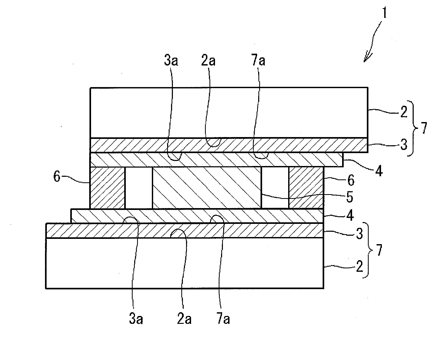
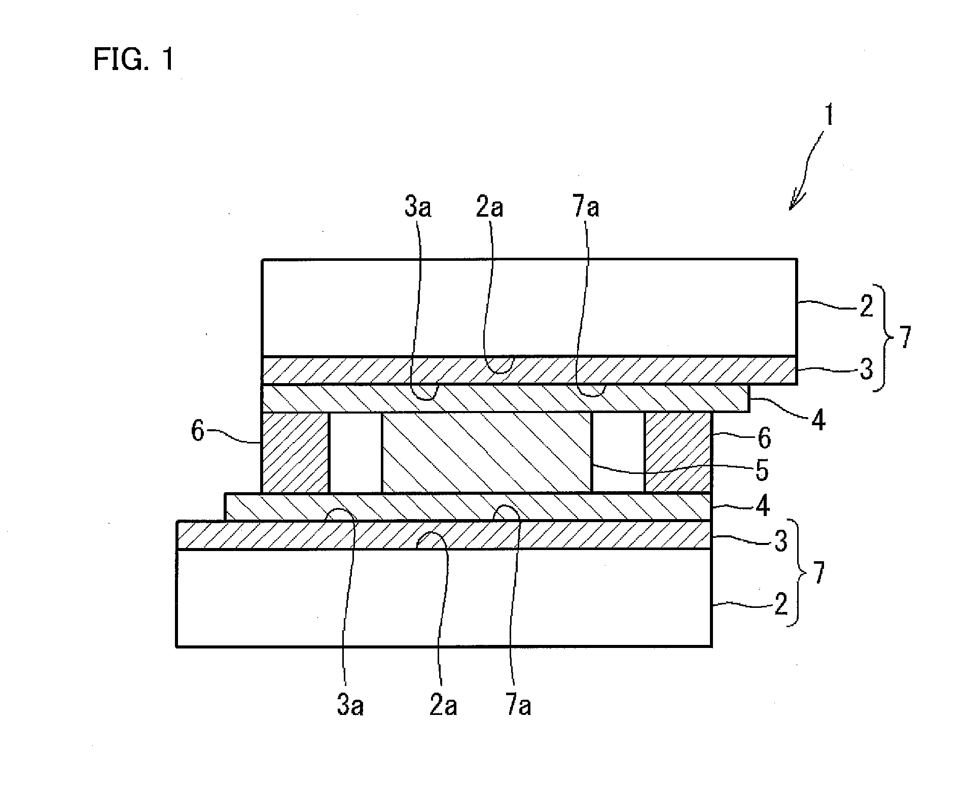
The present invention provides a fast-response photorefractive polymer element (1) including two insulating substrates (2, 2) arranged substantially in parallel with each other, ITO electrodes (3, 3) provided on inner surfaces (2a, 2a) of two insulating substrates (2, 2), dark current control layers (4, 4) provided on inner surfaces (3a, 3a) of ITO electrodes (3, 3), and a photorefractive composite material (5) provided between two insulating substrates (2, 2) with ITO electrodes (3, 3) and dark current control layers (4, 4). The photorefractive composite material (5) contains polytriarylamine (PTAA) which is a photorefractive polymer, and a dark current control layer (4) is a single-layered monomolecular film or multi-layered monomolecular films. With these configurations, a fast-response photorefractive polymer element achieves significantly improved responsiveness.
Description
TECHNICAL FIELD[0001]The present invention relates to a photorefractive polymer element, and specifically relates to a fast-response photorefractive polymer element in which a triphenylamine polymer is used as a host polymer.BACKGROUND ART[0002]A certain kind of material is known to have good charge transport property and its application encompasses the following photorefractive effect. The photorefractive effect is one of the nonlinear optical effects and is a phenomenon in which a refractive-index of a substance is changed when light is absorbed by the substance. The following description explains a mechanism of the photorefractive effect. When two laser beams are interfered with each other in a medium having photoconductivity and second-order optical nonlinearity, the interference fringes are formed. In a bright region of the interference fringes, charge carriers are generated by a photo-excitation. Positive charge carriers are moved in the medium with an assistance of an externa...
Claims
Login to View More Application Information
Patent Timeline
 IPC IPC(8): G02F1/39G02F1/35G02F1/361G02B27/42
CPCG02F1/397G02B27/4205G02F2001/3505G02F1/3501G02F1/3611G02B27/4233G03H2001/0264G03H2260/54G11B7/24044G11B7/245G11B7/246G02F1/3505
InventorTSUTSUMI, NAOTOKINASHI, KENJISHINKAI, HIRONORI
OwnerNAT UNIV KYOTO INST OF TECH