
Bedplate of a wind turbine

Inactive Publication Date: 2015-08-20
SIEMENS AG
View PDF3 Cites 2 Cited by
  • Summary
  • Abstract
  • Description
  • Claims
  • Application Information

AI Technical Summary

Benefits of technology

The invention proposes the use of new materials to create a bedplate for wind turbines that is stronger but lighter than traditional bedplates, reducing transportation, crane operation, and tower costs. Additionally, the bedplate can be coated to improve its resistance to environmental influences. The bedplate can serve as a transition piece for connecting a main bearing towards a rotor and / or a yaw bearing towards a tower. The angle between the first and second areas of the bedplate can be set between 70 to 90 degrees.

Problems solved by technology

These types of constructions can be made in large numbers, but have the disadvantage that they offer only moderate structural properties compared to the weight.

Method used


Image

  • Bedplate of a wind turbine
  • Bedplate of a wind turbine
  • Bedplate of a wind turbine

Examples


first embodiment

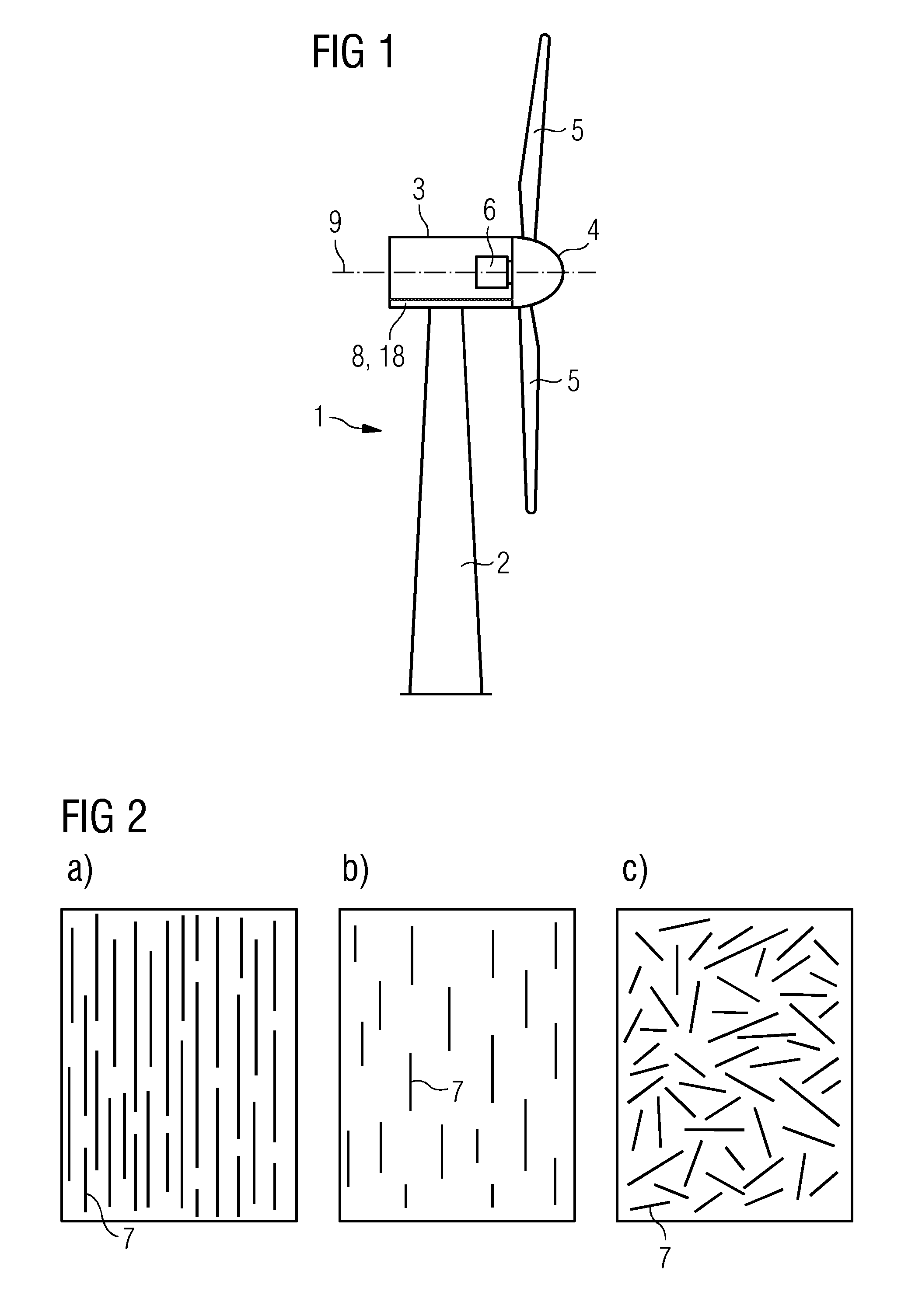
[0026]In a first embodiment, the fibers of at least a part of the reinforced material are configured as continuous fiber reinforced material. This is advantageous in that the fibers can be directed or extended in the directions where tension forces occur in the casted bedplate structure. In turn, this ensures that material can be saved as material in areas where there are low tension forces can be reduced.

second embodiment

[0027]In a second embodiment, the fibers of at least a part of the reinforced material are configured as discontinuous aligned fiber reinforced material.

third embodiment

[0028]In a third embodiment, the fibers of at least a part of the reinforced material are configured as discontinuous random oriented fiber reinforced material. This is advantageous in that the composite material has enhanced strengthening properties in substantially all directions, and thereby no special attention has to be put on how and where to orient the fibers.

[0029]In one embodiment, the reinforcement fibers are embedded in the composite material. This is advantageous in that it makes a very strong composite material.

[0030]In one embodiment, the reinforcement comprises reinforcement bars such as made of steel, plastics, carbon, glass-fiber etc. Hereby it is possible to reinforce the casted structure in load carrying directions. Even further such bars are easy to handle and does not require special attention on avoiding wrinkles etc. due to uneven lay up of fibers.

[0031]In one embodiment, the material of the fibers is at least one of steel, carbon, glass, Kevlar, basalt or any...


PUM


Abstract

The invention relates to a bedplate of a wind turbine comprising or made of a fiber-reinforced composite material.

Description

CROSS-REFERENCE TO RELATED APPLICATIONS[0001]This application claims priority to PCT Application No. PCT / EP2012 / 072882, having a filing date of Nov. 16, 2012, the entire contents of which are hereby incorporated by reference.FIELD OF TECHNOLOGY[0002]The following relates to a bedplate of a wind turbine.BACKGROUND[0003]In normal operation, the wind will generate loads on the rotor of the wind turbine. A major part of these loads will be transferred through various drive train components and through the bedplate to the wind turbine tower. The bedplate may be regarded as being a transition piece connecting the main bearing(s) towards the rotor at one side, and the yaw bearing towards the tower on the other side. However, the bedplate may take different basic shapes dependent on which wind turbine technology is used.[0004]EP 2136074 A illustrates one type of bedplate for the conventional wind turbine construction with a drive train comprising a main shaft and a gearbox. U.S. Pat. No. 7,...

Claims


Application Information

Patent Timeline
IPC IPC(8): F03D11/04F03D11/00
CPCY02E10/728F05B2240/14F05B2280/6003F03D13/20F03D80/88F03D80/70F03D80/80Y02E10/72
Inventor LIBERGREN, PETERLIND, SOEREN OEMANN
Owner SIEMENS AG
Features
  • Generate Ideas
  • Intellectual Property
  • Life Sciences
  • Materials
  • Tech Scout
  • Unparalleled Data Quality
  • Higher Quality Content
  • 60% Fewer Hallucinations
Learn More