Pump device

a pump and guide tube technology, applied in the direction of pump installation, non-positive displacement fluid engine, liquid fuel engine components, etc., can solve the problems of large pump electrical energy consumption, large electrical energy loss, and inability to customize the diameter of the guide tube closely, so as to achieve the effect of energy loss due to turbulence in the outlet flow

Inactive Publication Date: 2015-08-20
GRUNDFOS HLDG
View PDF3 Cites 0 Cited by
  • Summary
  • Abstract
  • Description
  • Claims
  • Application Information

AI Technical Summary

Benefits of technology

[0006]Thus, it is an object of the present invention to provide a pump device and corresponding pump system employing such a pump device according to which energy loss due to turbulence in the outlet flow of the pumped water is avoided.

Problems solved by technology

These large pumps consume a lot of electrical energy.
Most of the energy is imparted as energy to the water to be pumped, but a part of the energy is lost due to turbulence of water in a gap between a guide tube (volute) of the pump and an inner wall of the pipe.
However, in prior art pump systems, it is not possible to customize the diameter of the guide tube closely to the diameter of the inner wall of the pipe so as to close the gap and avoid turbulences.
If the fit is too narrow, then problems will arise during lowering the pump by means of the crane.

Method used


Image

  • Pump device
  • Pump device
  • Pump device

Examples


Embodiment Construction

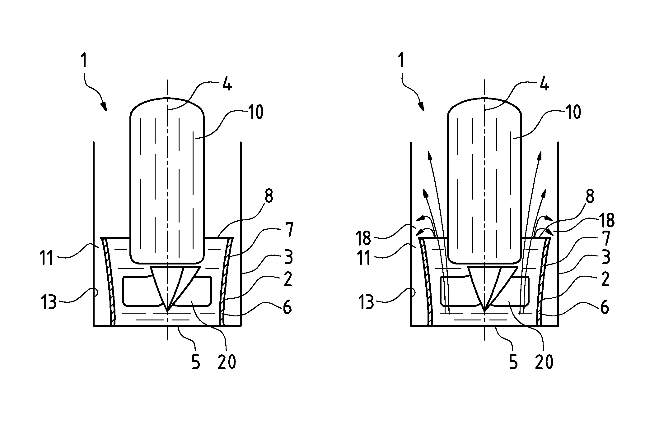
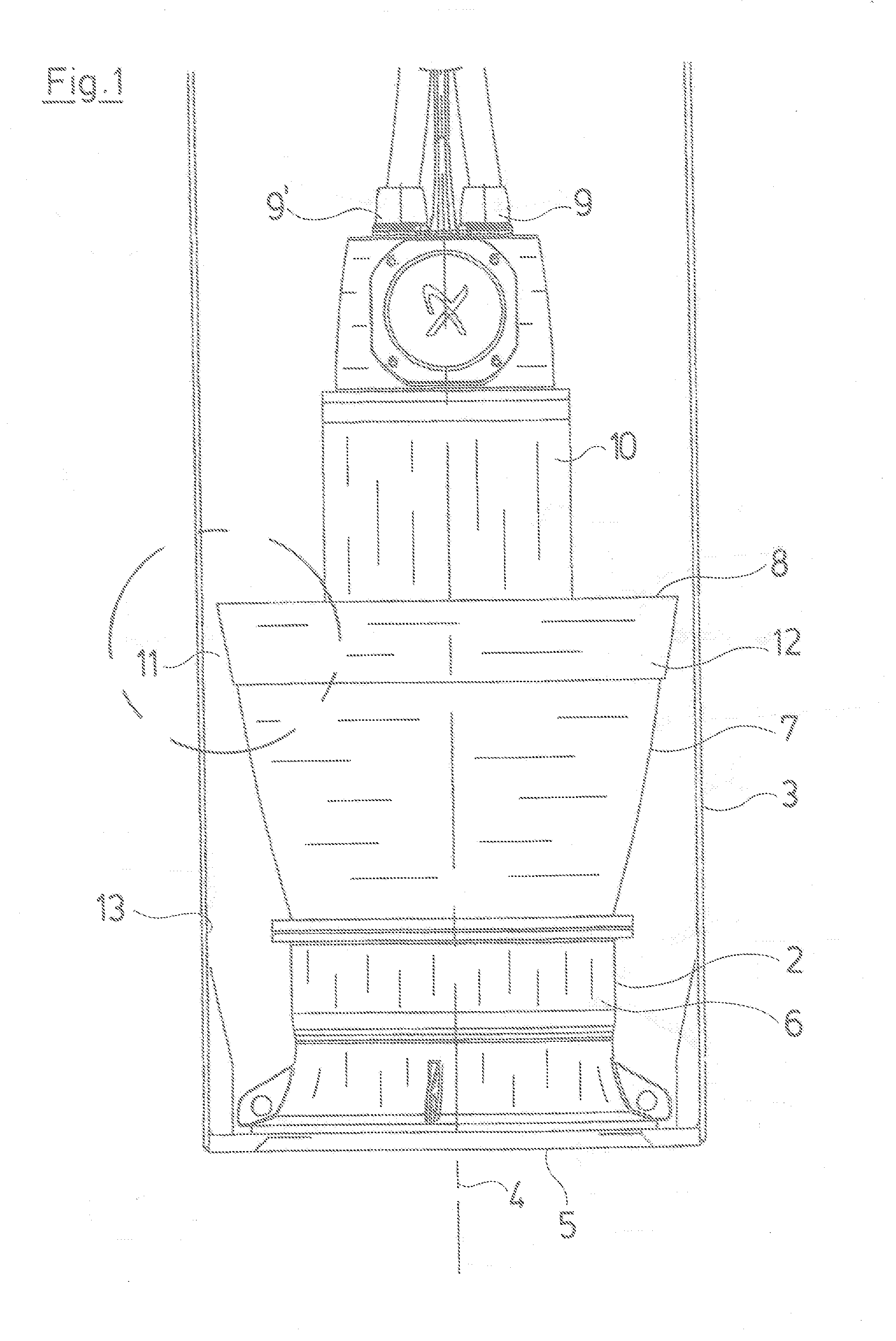
[0030]The pump system 1 comprises a pump device 2, which in this case is a submersible axial flow pump which is arranged in the center of a pipe in form of a column pipe 3. Specifically, the longitudinal axis 4 of the pump device 2 is arranged coaxially to the longitudinal axis of the pipe, in this case the column pipe 3. An axial flow pump in the meaning of the invention is a pump which propeller produces an axial flow. The invention may also be carried out with a mixed flow pump which uses an impeller which at least partly produces a radial flow which is deflected in axial direction by the surrounding volute or guide channel or guide tube, respectively. Thus, the mixed flow pump is a combination or compromise between a radial and an axial flow pump. The pump device 2 comprises an inlet portion 5 at its first axial end, in this case the lower end at which water enters the pump. Inside the pump housing 6 a propeller portion with diffuser vanes and an axial propeller is arranged. Als...


PUM


Abstract

A pump device (2), to be mounted coaxially in a pipe (3), includes an axial or mixed flow pump with a guide tube (7) arranged around a propeller portion of the pump device (2). In a mounting position, a gap (11) is formed between an upper end (16) of the guide tube (7) at an outlet portion (8) of the pump device (2) and the column pipe (3). The guide tube (7) has an elastic portion (12) connected to an outlet end of the guide tube (7). The elastic portion (12) is bendable in a radial direction towards the column pipe (3) in order to at least partially, in particular completely, close the gap (11) during operation of the pump device (2). Further, a pump system (1) includes the pump device (2).

Description

CROSS REFERENCE TO RELATED APPLICATIONS[0001]This application is a U.S. National Phase Application of International Application PCTEP2013061204 filed May 30, 2013 and claims the benefit of priority under 35 U.S.C. §119 of European Patent Application EP 12 184 888.1 filed Sep. 18, 2012, the entire contents of which are incorporated herein by reference.FIELD OF THE INVENTION[0002]The present invention to a pump device to be mounted coaxially in a pipe, the pump device comprising an axial or mixed flow pump with a guide tube arranged around a propeller portion of the pump device and to a pump system.BACKGROUND OF THE INVENTION[0003]Axial flow or mixed flow pumps are typically used where large amounts of water have to be moved, for example for removing water from flooded areas. These pumps may be equipped with motors with a power range from 10 kW to 1 MW and usually are placed inside a pipe or column pipe such that the pipe coaxially surrounds the pump. The column pipe in particular ext...

Claims


Application Information

Patent Timeline
Patent Type & Authority Applications(United States)
IPC IPC(8): F04D29/08F04D25/06F04D29/66F04D19/02
CPCF04D29/566F04D19/028F04D25/0686F04D29/086F04D29/669
Inventor JESSEN, ALLAN
Owner GRUNDFOS HLDG
Why Eureka
Try Eureka