

Proportional jog controls
- Summary
- Abstract
- Description
- Claims
- Application Information
AI Technical Summary
Benefits of technology
Problems solved by technology
Method used
Image

Examples
Embodiment Construction
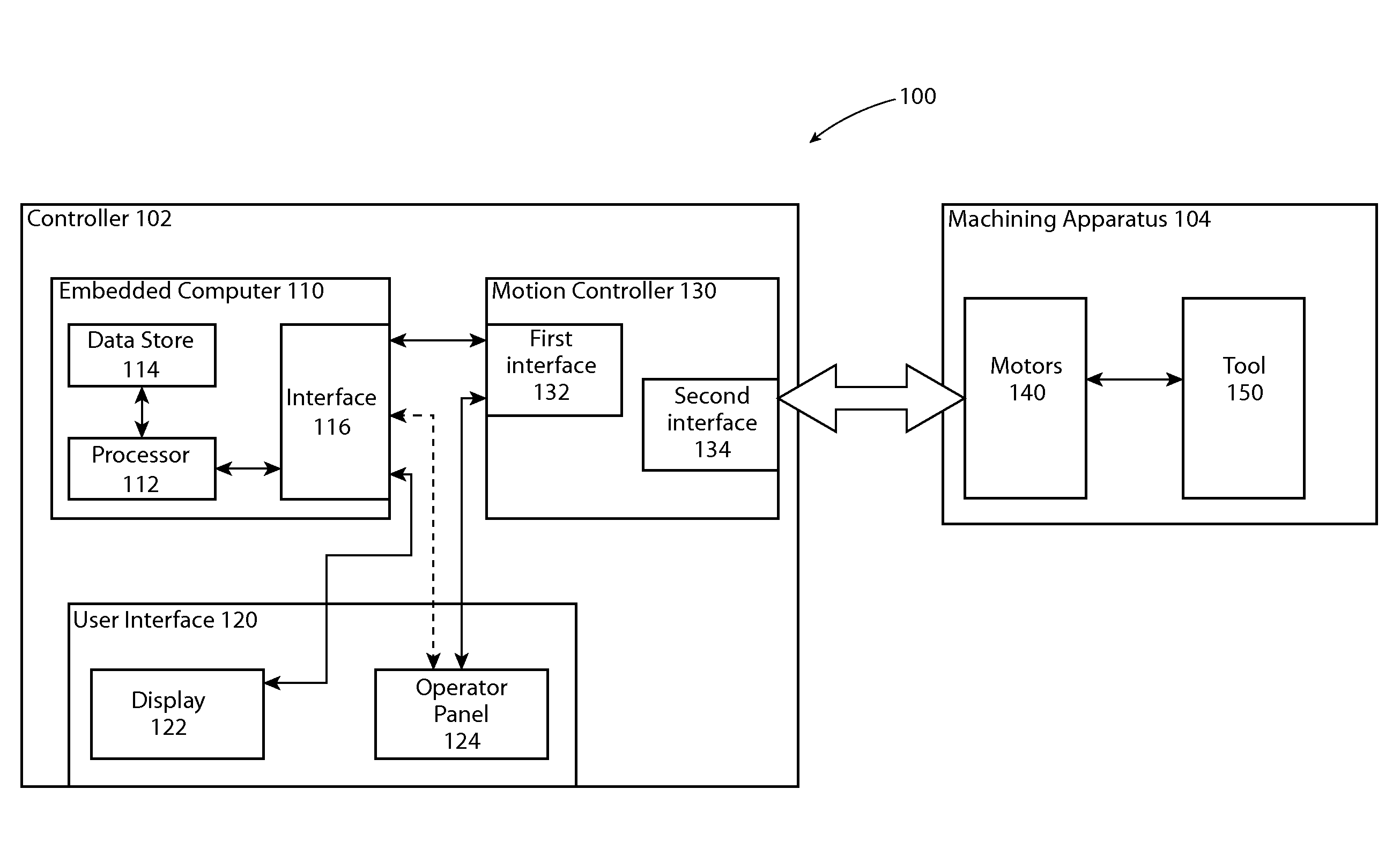
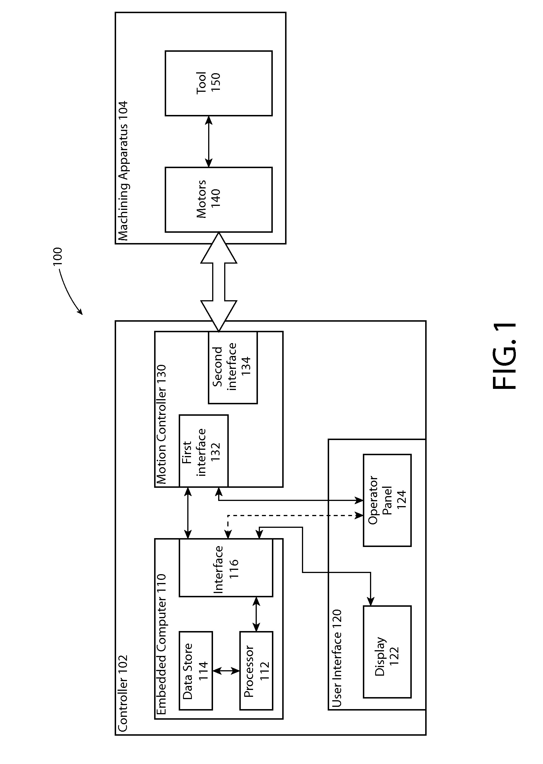
[0022]Embodiments of the invention relate to systems and methods for jog operations performed on a machining apparatus. As utilized herein, a “machining apparatus” is a device or system for performing a machining operation. A machining operation can include various actions performed on a workpiece such as, but not limited to, cutting, marking, routing, grinding, milling, lathing, sawing, drilling, boring, etc. The jog operations involve a variable feed rate generated proportionally to an degree to which a jog control is engaged by an operator. Exemplary embodiments will now be described with reference to the drawings. The examples and drawings are illustrative only and not meant to limit the invention, which is measured by the scope and spirit of the claims. Like reference numerals refer to like elements throughout.
[0023]FIG. 1 illustrates one example of a CNC machining system 100 capable of performing a machining operation. As shown in FIG. 1, system 100 includes a controller 102 c...
PUM
 Abstract
Description
Claims
Application Information