Cache memory controller and cache memory control method

a controller and cache technology, applied in the field of cache memory controller and cache memory control method, can solve the problems of difficult replacement of the entire main memory with a cache memory, low capacity per unit area, high cost, etc., and achieve the effect of reliably obtaining cache hits

Inactive Publication Date: 2015-08-20
MITSUBISHI ELECTRIC CORP
View PDF2 Cites 8 Cited by
  • Summary
  • Abstract
  • Description
  • Claims
  • Application Information

AI Technical Summary

Benefits of technology

[0010]These aspects of the present invention enable cache hits to be reliably o

Problems solved by technology

Cache memories, however, are expensive and have a low capacity per unit area, so in most cases it would be difficult to replace the

Method used


Image

  • Cache memory controller and cache memory control method
  • Cache memory controller and cache memory control method
  • Cache memory controller and cache memory control method

Examples


first embodiment

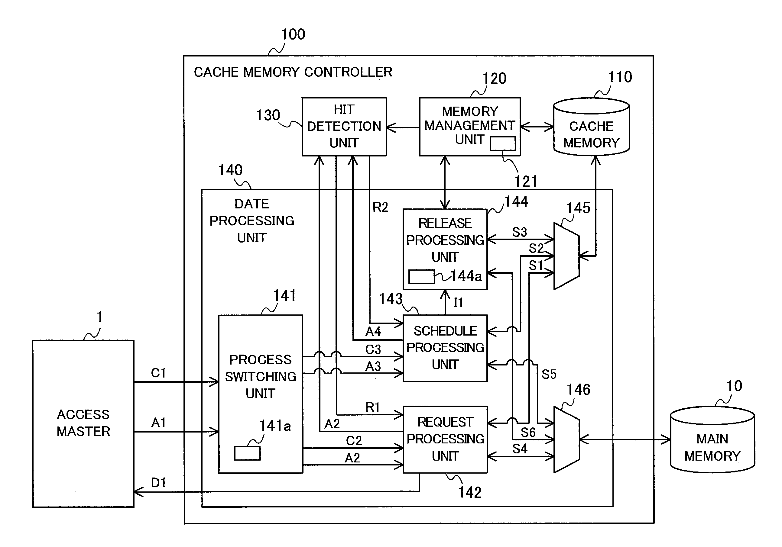
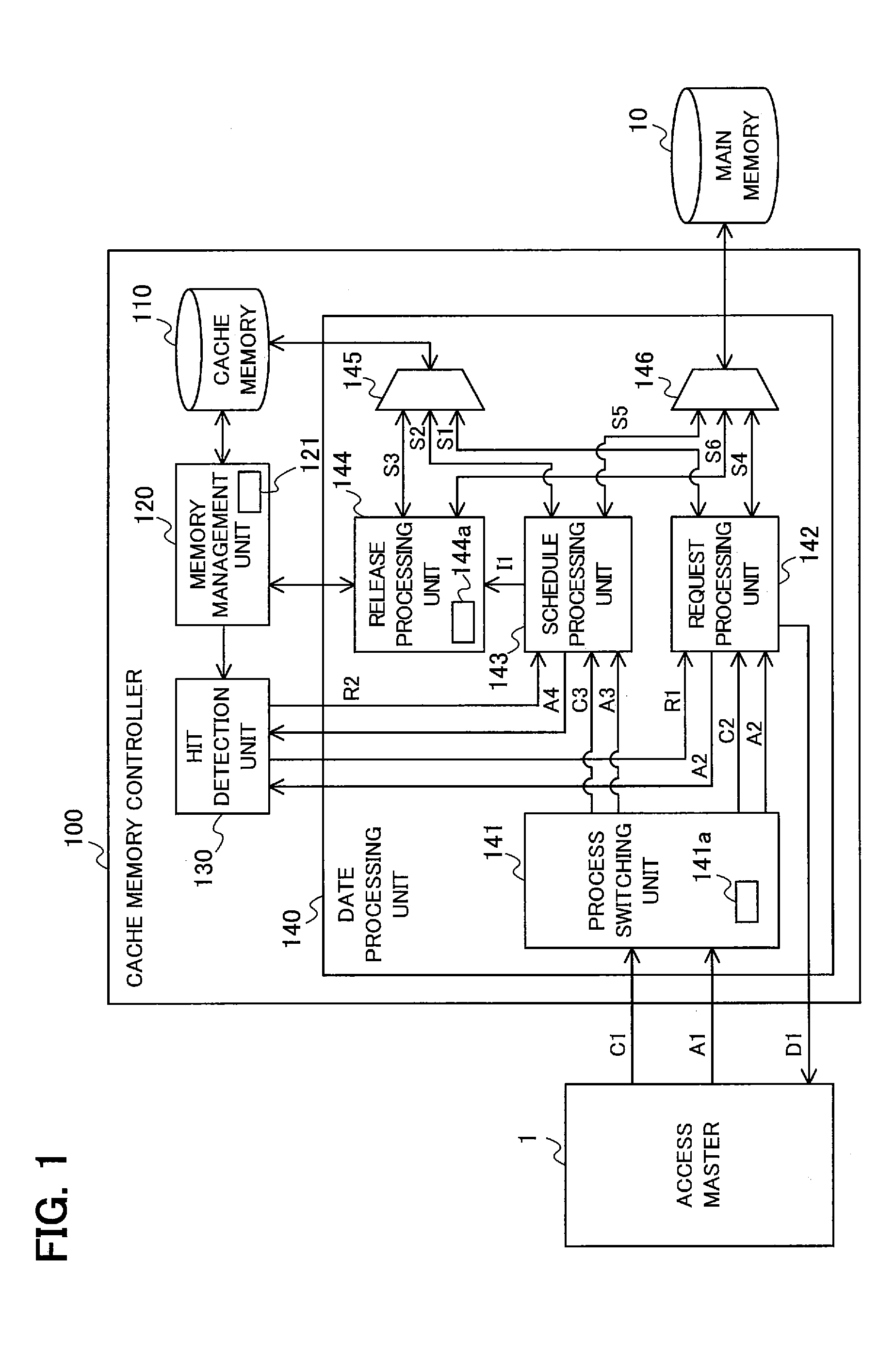
[0041]FIG. 1 is a block diagram schematically showing the configuration of the cache memory controller 100 according to the first embodiment. The cache memory controller 100 includes a cache memory 110, a memory management unit 120, a hit detection unit 130, and a data processing unit 140.

[0042]The connection relationships among an access master 1, the cache memory controller 100, and a main memory 10 are shown in FIG. 1 in a simplified form. On the basis of an instruction command C1 from the access master 1, the cache memory controller 100 accesses data stored in the cache memory 110, which will be described later, or the main memory 10. Here, the instruction command C1 is a request from the access master 1 for access to an address on the main memory 10. If, for example, the instruction command C1 is a read request, the instruction command C1 and an instruction address A1 that indicates the address on the main memory 10 are input from the access master 1 to the cache memory control...

second embodiment

[0127]The second embodiment will be described with reference to FIGS. 16 to 30.

[0128]FIG. 16 is a block diagram schematically showing the configuration of a cache memory controller 200 according to the second embodiment. The cache memory controller 200 includes a cache memory 110, a memory management unit 120, a hit detection unit 130, and a data processing unit 240.

[0129]FIG. 16 shows the connection relationships among an access master 1, the cache memory controller 200, and the main memory 10 in a simplified form.

[0130]The main memory 10 is managed in collective units of a certain capacity, referred to as banks. A bank is divided into an instruction area and a data area. It is possible to access a specific continuous area by designating its row (Row) address and column (Column) address in the main memory 10.

[0131]The functions of the cache memory 110, memory management unit 120, and hit detection unit 130 are the same as in the first embodiment and have already been described, so ...


PUM


Abstract

A cache memory controller (100) connected to a main memory (10) having an instruction area storing a first program and a data area storing data used by a specific instruction included in the first program, and to an access master (1) for executing instructions included in the first program. The cache memory controller is provided with a cache memory (110) for storing a portion of the data in the main memory (10), and a data processing unit (140) that, prior to execution of the specific instruction by the access master (1), and in accordance with transfer scheduling information including the starting address of the specific instruction, calculates an access interval on a basis of the number of instruction steps remaining from the address of the instruction currently being executed by the access master (1) to the starting address of the specific instruction, and transfers data used by the specific instruction from the main memory (10) to the cache memory (110) at this access interval.

Description

TECHNICAL FIELD[0001]The present invention relates to a cache memory controller and a cache memory control method.BACKGROUND ART[0002]The amounts of data in the computer programs, images, and so on that devices deal with has been increasing over recent years, and the capacities of the hard disks and main memories installed in the devices have been increasing as well. A main memory is divided into an instruction area and a data area. Program instructions and other instructions are stored in the instruction area; image data and other data used in processing by the instructions are stored in the data area. Since the main memory operates at a lower cycle speed than the CPU or other access master, a cache memory that can be accessed at high speed is generally employed. By accessing the cache memory, the access master can read and write data faster.[0003]Cache memories, however, are expensive and have a low capacity per unit area, so in most cases it would be difficult to replace the enti...

Claims


Application Information

Patent Timeline
IPC IPC(8): G06F12/08G06F12/0862G06F12/0875
CPCG06F12/0875G06F2212/452G06F2212/1024G06F12/0862G06F2212/6028
Inventor TANAKA, SAORIKIJIMA, JUNKONAITO, MASAHIRO
Owner MITSUBISHI ELECTRIC CORP
Why Eureka
Try Eureka