
Depth image enhancement method

a depth image and enhancement technology, applied in image enhancement, image analysis, instruments, etc., can solve problems such as problems such as stereovision images and structured light, and achieve the effect of increasing the homogeneity of intensity

Active Publication Date: 2015-08-20
IEE INT ELECTRONICS & ENG SA
View PDF2 Cites 48 Cited by
  • Summary
  • Abstract
  • Description
  • Claims
  • Application Information

AI Technical Summary

Benefits of technology

The patent describes a method to make sure that depth information is accurate in an image. It does this by using a blending map that adjusts the importance of different pixels in the depth image based on the intensity of nearby pixels in an intensity image. This helps to make the depth image more accurate and consistent.

Problems solved by technology

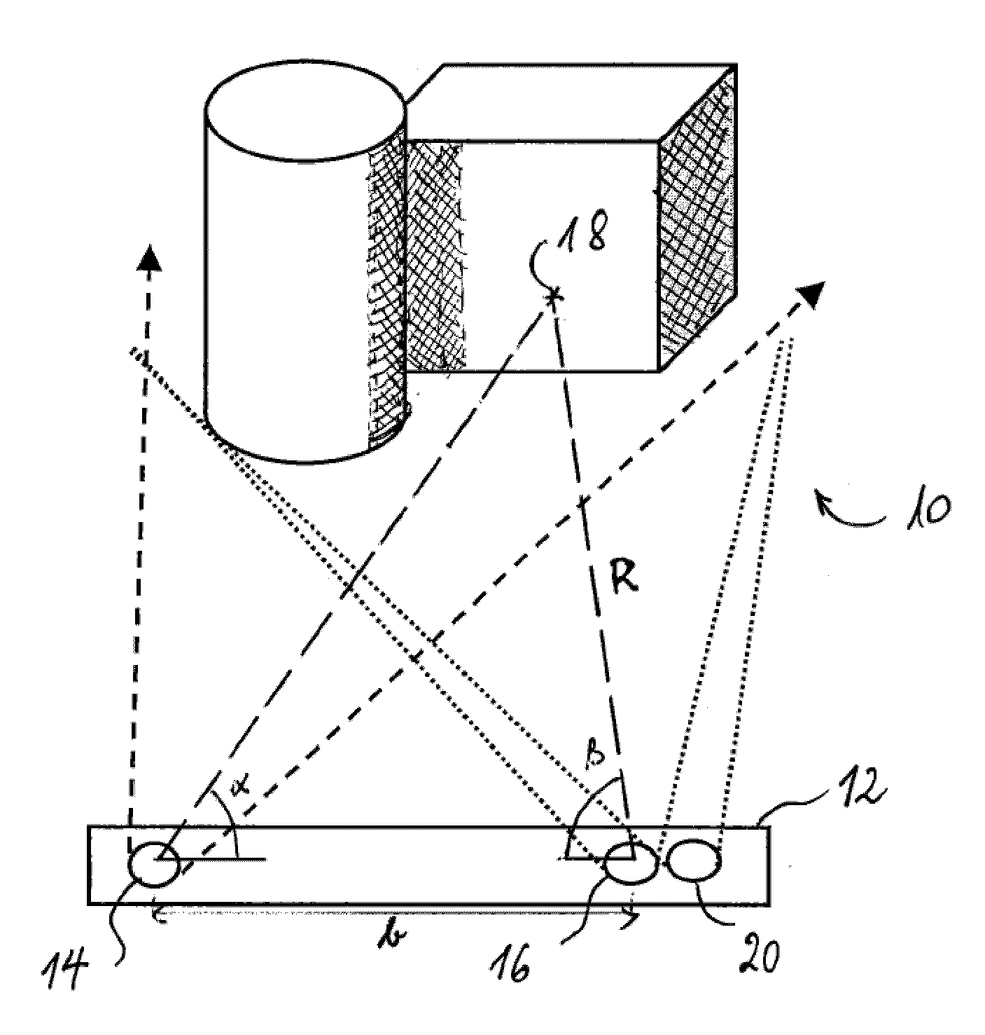
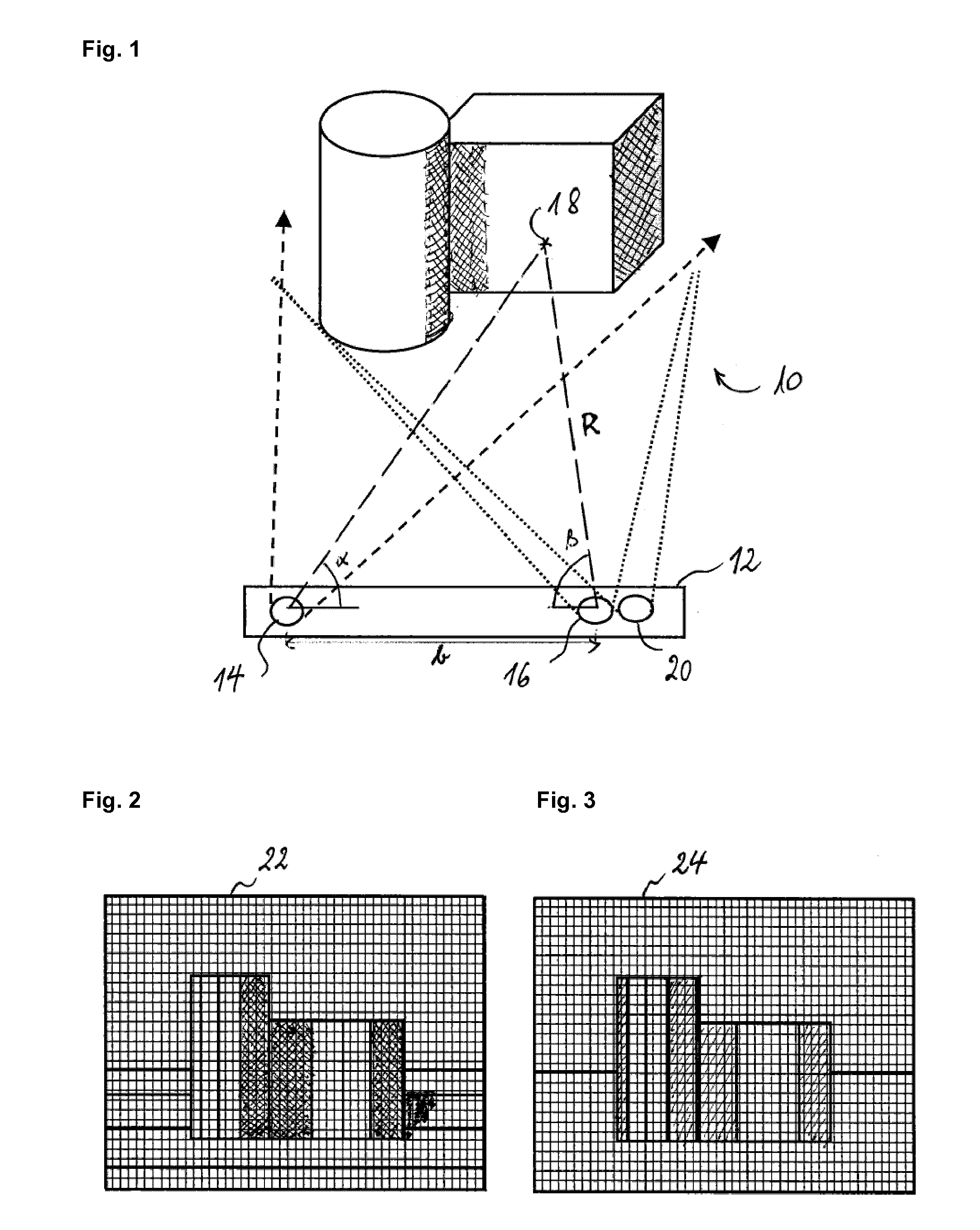
As indicated above, problems may arise with the structured light when the reflected light power of the projected pattern is not strong enough to be detected by the sensor.
Furthermore, since active triangulation methods require a baseline for depth estimation, there are always shadowed regions in which not depth value can be determined.
As similar problem exists with depth images obtained by stereovision.

Method used


Image

  • Depth image enhancement method
  • Depth image enhancement method
  • Depth image enhancement method

Examples


1st embodiment

1st Embodiment

[0050]According to a first preferred embodiment of the invention, a first filtered depth image {J′2(p)}p is calculated by applying a first filter to the depth image, expressible as follows:

J2′(p)=∑q∈N(p)fS(p,q)fI(I(p),I(q))W(q)R(q)∑q∈N(p)fS(p,q)fI(I(p),I(q))W(q).(Eq.7)

This first filter is a cross bilateral filter that averages over pixels in the depth image {R(p)}p while weighting contributions of the pixels over which is averaged by similarity of corresponding pixels in the intensity image {I(p)}p. In the above equation, fS(.,.) is a spatial weighting term that applies to the pixel position p, and fI(.,.) is a range weighting term that applies to the pixel value I(p). The weighting functions fS(.,.) and fI(.,.) are Gaussian functions with standard deviations σS and σI, respectively. The weighting map {W(p)}p is defined by:

W(p)=V(p)·QR(p),  (Eq. 8)

where V is the occlusion map and

QR(p)=exp(-(∇R(p))22σQ2)(Eq.9)

defines the so-called “credibility map” Q. ∇R(p) represents t...

2nd embodiment

2nd Embodiment

[0060]According to a second preferred embodiment of the invention, the enhanced depth image (noted {J″4(p)}p) is calculated by:

J″4(p)=(1−B(p))·J′2(p)+B(p)·R(p),  (Eq. 16)

where the above definition of J′2(p) still holds (Eq. 7) and where the blending map B may be defined as in any one of equations 12, 13 and 15.

[0061]The calculation of the enhanced range image by equation 16 differs from the calculation according to equation 11 only in that the depth map R replaces the second filtered range image J′3. Eq. 11 may be preferred over eq. 16 if the depth image R is noisy. In the noise level of the depth image is low, one should prefer calculation based on eq. 16, which is less computationally costly.

[0062]For real-time application, computation of the first (and possibly the second) filtered depth image and of the blending map in full resolution may be unsuitable. (However, this depends on the available hardware.) One may use downsampled versions of the depth image and of the...


PUM


Abstract

A method for enhancing a depth image of a scene, comprises calculating an enhanced depth image by blending a first filtered depth image with a second filtered depth image or with the original depth image. The blending is achieved by application of a blending map, which defines, for each pixel, a contribution to the enhanced depth image of the corresponding pixel of the first filtered depth image and of the corresponding pixel of either the second filtered depth image or the original depth image. For pixels in the depth image containing no depth value or an invalid depth value, the blending map defines a zero contribution of the corresponding pixel of the second filtered depth image and a 100% contribution of the corresponding pixel of the first filtered image.

Description

TECHNICAL FIELD[0001]The present invention generally relates to the field of image processing, in particular, to enhancing a depth image when a corresponding intensity image is available.BACKGROUND ART[0002]Computer vision applications based on 3D imaging (three-dimensional imaging) have gained increasing attention from the scientific community in the recent years. This is due, at least in part, to a growing demand in industry for autonomous systems capable of sensing the shape and location of objects in a scene.[0003]In recent years, 3D cameras based on the Time-of-Flight (ToF) principle have become commercially available. Compared to 2D cameras, they measure, for each pixel, a radial distance of a point in the scene to the camera, while 2D cameras provide only a gray- or color image of the scene (hereinafter referred to as “intensity image”). Other 3D imagers are based on triangulation. Passive triangulation (without active illumination of the scene) is known as stereopsis or ster...

Claims


Application Information

Patent Timeline
Patent Type & Authority Applications(United States)
IPC IPC(8): G06T5/00G06T7/00H04N13/122
CPCG06T2207/10028G06T2207/20012G06T2207/20028G06T2207/20221H04N2013/0081H04N13/122G06T7/593G06T5/70
Inventor MIRBACH, BRUNOSOLIGNAC, THOMASGARCIA BECERRO, FREDERICAOUADA, DJAMILA
Owner IEE INT ELECTRONICS & ENG SA
Learn More