PPTC over-current protection device
- Summary
- Abstract
- Description
- Claims
- Application Information
AI Technical Summary
Benefits of technology
Problems solved by technology
Method used
Image

Examples
example 1
EX1
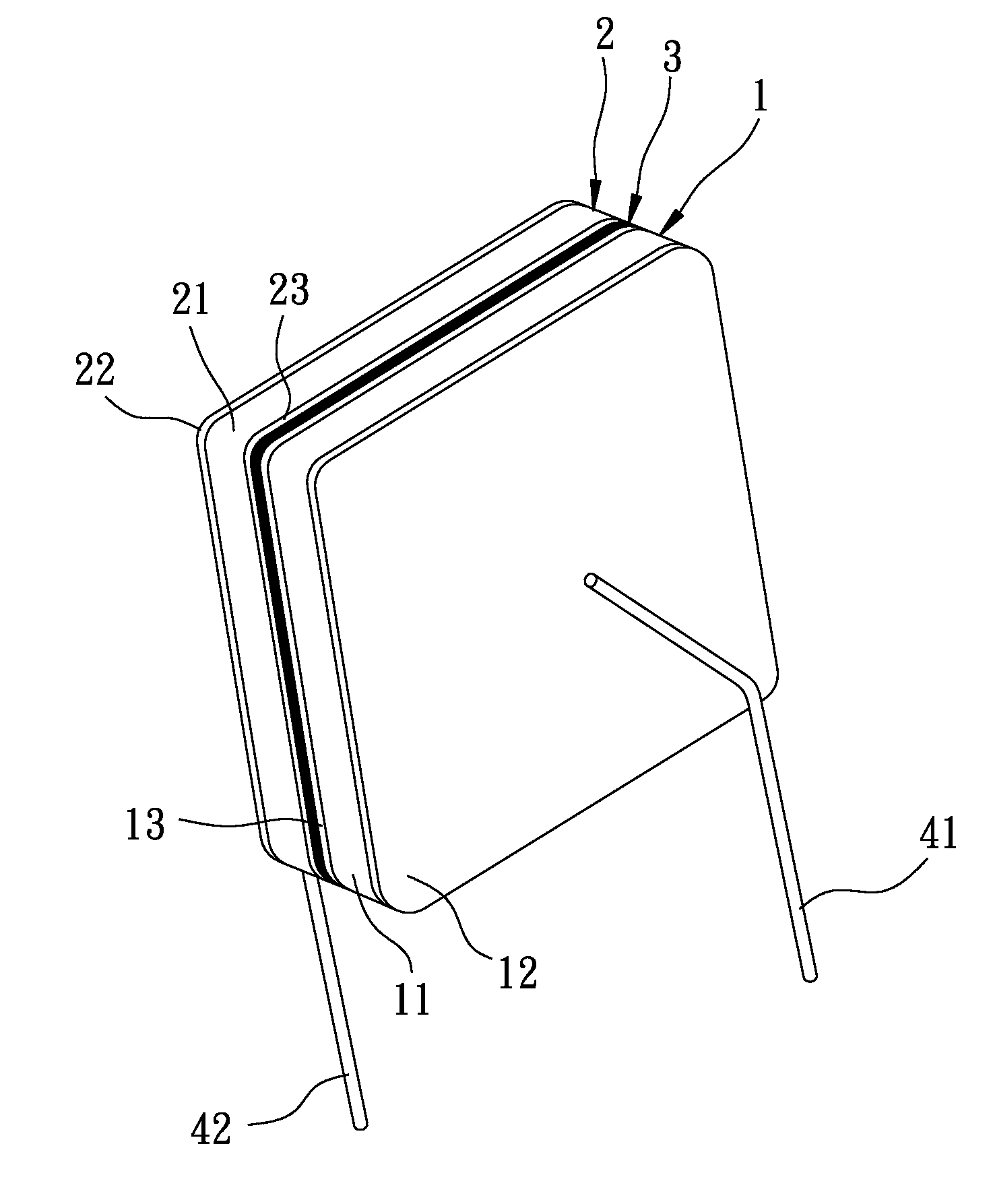
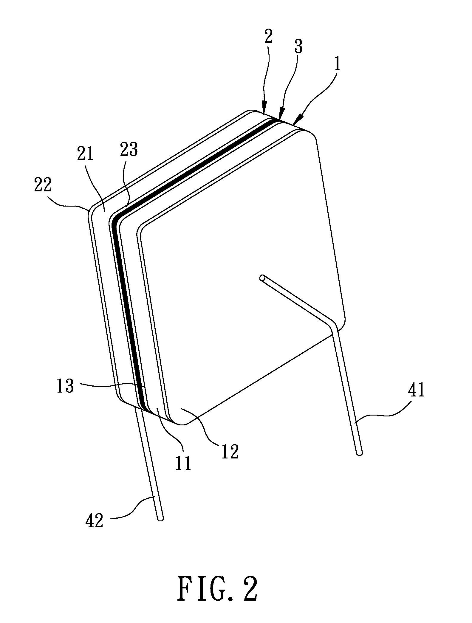
[0036]Two PPTC components A were irradiated by cobalt-60 sources. Each of the PPTC components A had a total radiation dose of 150 kGy. One of the PPTC components A served as the first PPTC component and the other served as the second PPTC component. One of the copper foil sheets of the first PPTC component A was stacked on and was soldered to one of the copper foil sheets of the second PPTC component A through a solder material, followed by soldering first and second conductive leads to the two opposite end faces of the stack, that are defined by the other of the copper foil sheets of the first PPTC component A and the other of the copper foil sheets of the second PPTC component A, using the solder material, respectively.
[0037]The trip times obtained under different applied voltages and different trip currents and the resistance of the PPTC over-current protection device of Example 1 were measured. The test results are shown in Table 2.
example 2
EX2
[0038]Two PPTC components A1 were irradiated by cobalt-60 sources. Each of the PPTC components A1 had a total radiation dose of 150 kGy. One of the PPTC components A1 served as the first PPTC component and the other served as the second PPTC component.
[0039]The first polymer matrix of the first PPTC component A1 was stacked on and was interfusion-bonded to the second polymer matrix of the second PPTC component A1, followed by soldering first and second conductive leads to the two opposite end faces of the stack, that are defined by the copper foil sheet of the first PPTC component A1 and the copper foil sheet of the second PPTC component A1, using the solder material, respectively.
[0040]The trip times obtained under different applied voltages and different trip currents and the resistance of the PPTC over-current protection device of Example 2 were measured. The test results are shown in Table 2.
examples 3 to 6
EX3 to EX6
[0041]The procedures and conditions in preparing the PPTC over-current protection device of each of Examples 3 to 6 were similar to those of Example 1, except for the compositions of the first and second PPTC elements of the first and second PPTC components (see Table 2).
[0042]The trip time obtained under different applied voltages and different trip currents and the resistance of the PPTC over-current protection devices of each of Examples 3 to 6 were measured. The test results are shown in Table 2.
PUM
 Abstract
Description
Claims
Application Information
 - R&D Engineer
- R&D Manager
- IP Professional
- Industry Leading Data Capabilities
- Powerful AI technology
- Patent DNA Extraction
Browse by: Latest US Patents, China's latest patents, Technical Efficacy Thesaurus, Application Domain, Technology Topic.
© 2024 PatSnap. All rights reserved.Legal|Privacy policy|Modern Slavery Act Transparency Statement|Sitemap