Uniform force flange clamp

a clamping device and flange technology, applied in the field of clamps, can solve the problems of unusable previous clamping devices for many applications, and achieve the effects of uniform clamping pressure, fast application and use, and high hea

Inactive Publication Date: 2015-08-20
GENERAL PLASMA
View PDF4 Cites 12 Cited by
  • Summary
  • Abstract
  • Description
  • Claims
  • Application Information

AI Technical Summary

Benefits of technology

[0008]A clamp is provided that incorporates a plurality of flexible links with ‘v’ flexures between the links to maintain even spacing of the links before and during installation. In embodiments of the inventive clamp, each link has multiple segments joined at a center flexure point, and a floating band surrounding the links to adjust an evenly distributed clamping pressure that is produced along a circumference of contact points provided by the link segments. Embodiments of the present inventive clamp provide evenly distributed clamping pressure by increasing the number of clamping contact points between the inventive clamp and an application device or apparatus to be secured. Embodiments of the inventive clamps have non-limiting applications for clamping target tubes or as a vacuum flange for ISO fittings. Embodiments of the inventive clamp produce a vacuum tight seal between a target tube and end block or end support flange without requiring tools, and is very fast to apply and use by a technician.
[0009]Embodiments of the inventive clamp employ a floating band

Problems solved by technology

In embodiments, as the floating band is tightened the links are not pulled around with the band itself, as encountered in previous de

Method used


Image

  • Uniform force flange clamp
  • Uniform force flange clamp
  • Uniform force flange clamp

Examples


Embodiment Construction

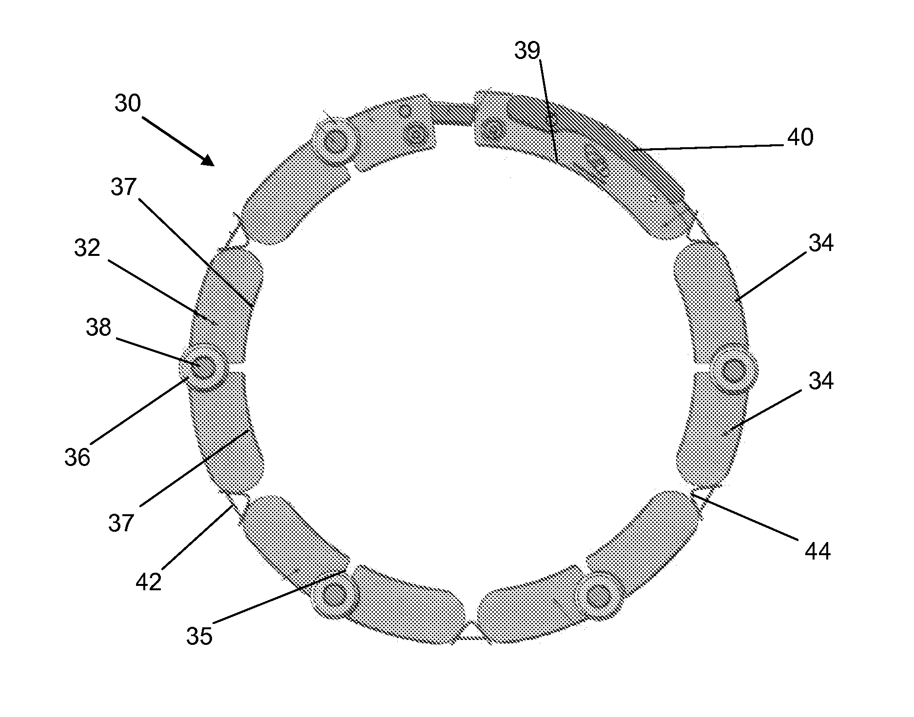
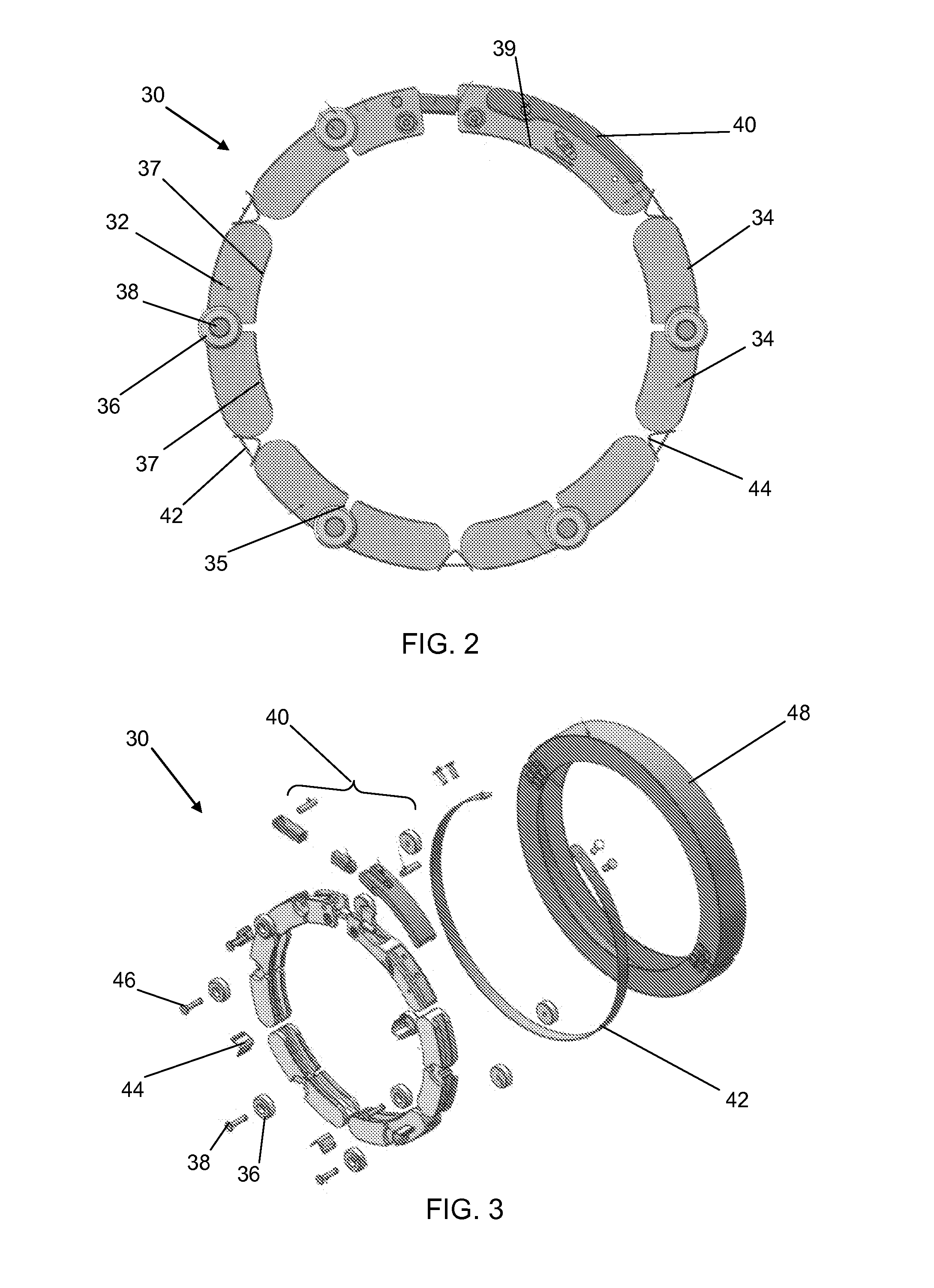
[0024]The present invention has utility as a clamp. The present invention discloses a clamp incorporating a plurality of flexible links with ‘v’ flexures between the links to maintain even spacing of the links before and during installation, where each link has at least two segments joined around at least one flexure point, and a floating band surrounding the links to adjust the distribution of clamping pressure that is produced along a circumference of contact points with the articles being joined. An inventive clamp has the benefits multiple contact points around sealing flanges thereby reducing deformation on the jointed articles; more uniform clamping force at each contact point; no necessity for tools to engage or disengage the clamp and therefore is quicker to deploy and remove; compliant members between links keeps links properly spaced at initial installation and then allow links to move inward, and closer together, as they are tightened around a joinder.

[0025]Embodiments of...


PUM

PropertyMeasurementUnit
Pressureaaaaaaaaaa
Flexibilityaaaaaaaaaa
Circumferenceaaaaaaaaaa

Abstract

A clamp is provided that incorporates a plurality of flexible links with V flexures between the links to maintain even spacing of the links before and during installation. Each link has multiple segments joined around at least one flexure point, and a floating band surrounding the links to distribute clamping pressure that is produced along a circumference of contact points. The clamp provides evenly distributed clamping pressure by increasing the number of clamping contact points between the clamp and articles being joined. The clamp has non-limiting applications for clamping target tubes or as a vacuum flange for ISO fittings. A clamp can produce a vacuum tight seal between a target tube and end block or end support flange of a rotary magnetron without resort to tools, and as such is rapidly secured in place.

Description

CROSS-REFERENCE TO RELATED APPLICATION[0001]This application claims priority of United States Provisional Patent Application Ser. No. 61 / 703,249 filed Sep. 19, 2012, which is incorporated herein by reference.FIELD OF THE INVENTION[0002]The present invention generally relates to clamps. More specifically, the present invention discloses a clamp incorporating a plurality of flexible links with ‘v’ flexures between the links to maintain even spacing of the links before and during installation, where each link has multiple segments joined at a center flexure point, and a floating band surrounding the links to adjust an evenly distributed clamping pressure that is produced along a circumference of contact points provided by the link segments.BACKGROUND OF THE INVENTION[0003]The International Organization for Standardization that is widely known as ISO, is an international standard-setting body composed of representatives from various national standards organizations. The ISO promulgates ...

Claims


Application Information

Patent Timeline
IPC IPC(8): H01J37/34B25B5/14F16B2/08
CPCH01J37/3435H01J37/3455B25B5/147F16B2/08Y10T29/49947
Inventor MADOCKS, JOHN E.LOHRENZ, RYANSMITH, SR., STEVEN
Owner GENERAL PLASMA
Why Eureka
Try Eureka