Pulse cleaning filter system arrangement

Active Publication Date: 2015-08-27
AMEC FOSTER WHEELER IND POWER CO INC
1 Cites 6 Cited by

AI-Extracted Technical Summary

Problems solved by technology

The gas pulses remove particulate matter collected on the inlet surfaces of the filter cartridges, which tends to reduce the flow resistance of the filter system.
The immersion style pulse headers are relatively expensive to fabricate and to install.
The immersion type headers have the drawback of the internal blowpipes reducing the free volume available for the compressed air to be stored in the air header.
Moreover, bending and installing of the bl...

Benefits of technology

[0020]Because the pulse valves according to the present invention are not immersion-type valves arranged within the compressed gas header as, e.g., in the U.S. Patent Application Publication No. 2008/0022856 A1, issued as U.S. Pat. No. 7,585,343 B2 on Sep. 8, 2009, but right angle pulse valves connecting the stub pipes to pulse manifold pipes, the pulse valves do not decrease the free volume of the gas header. Therefore, the present pulse valves are advantageous for providing relatively large compressed gas pulses. Because the pulse valves are not within the gas header, but outside of the header, the size of the pulse valves is not restricted. Thus, the pulse valves according to the present invention enable larger flow channels and higher gas flow rates, and thus, higher capacity cleaning pulses, than do conventional immersion-type valves.
[0021]Becau...

Abstract

A pulse cleaning filter system has a housing with an inlet side and an outlet side separated by a planar tubesheet. The housing includes multiple tubesheet openings forming multiple rows. Multiple cylindrical filter cartridges have an open end sealed around one of the tubesheet openings and a closed end at the inlet side of the housing. A filter cleaning system includes a compressed gas header extending perpendicular to a normal of the tubesheet, multiple compressed gas outlet stub pipes extending from the header, right angle pulse valves connecting each of the stub pipes to a pulse manifold pipe including a first straight portion, a ninety degree bend at the outlet side of the housing, and a second straight portion at the outlet side of the housing. A gas pulse nozzle has a main injection axis directed along the central axis of the filter cartridge.

Application Domain

Dispersed particle filtrationTransportation and packaging +2

Technology Topic

NozzleFilter system +2

Image

  • Pulse cleaning filter system arrangement
  • Pulse cleaning filter system arrangement
  • Pulse cleaning filter system arrangement

Examples

  • Experimental program(1)

Example

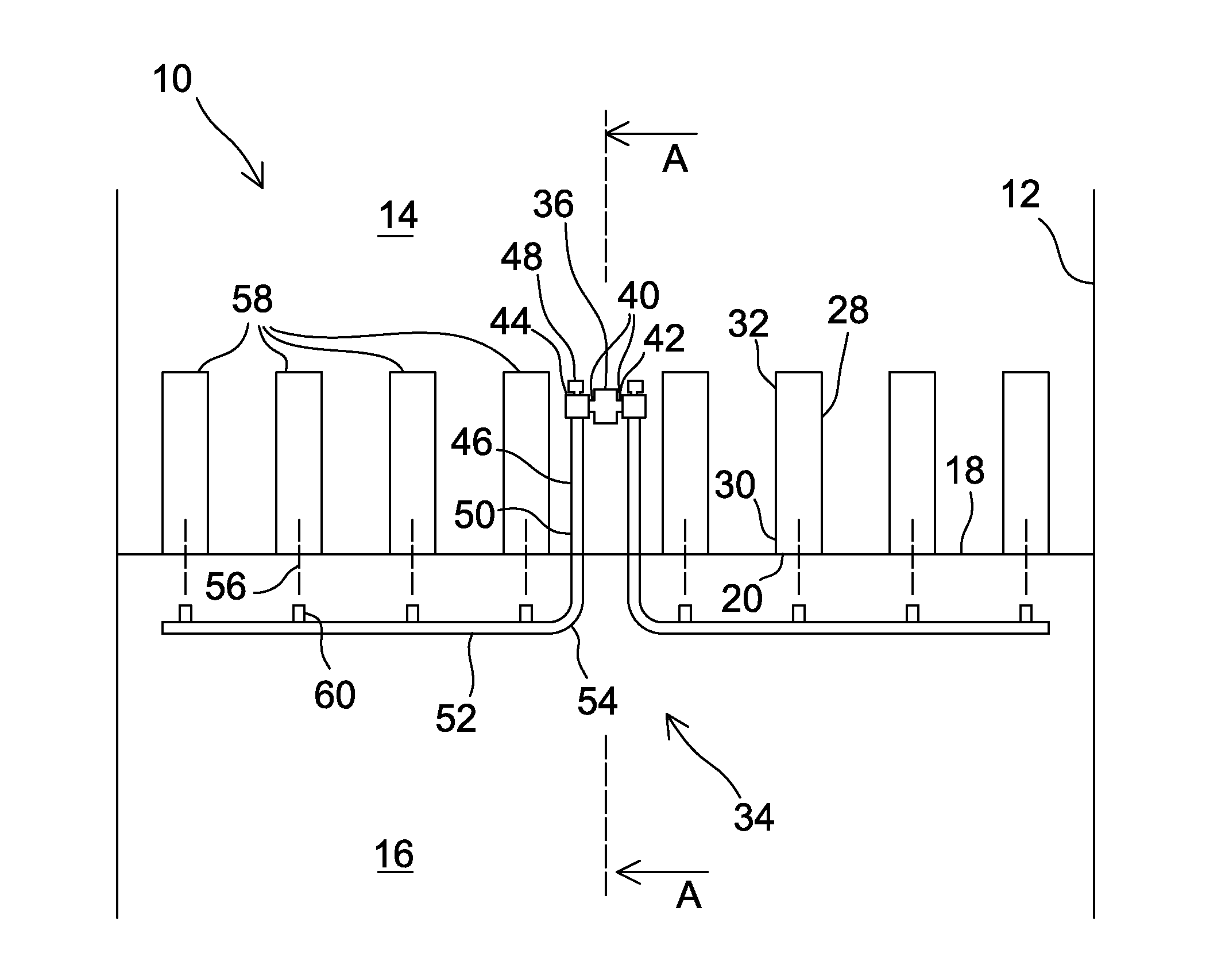
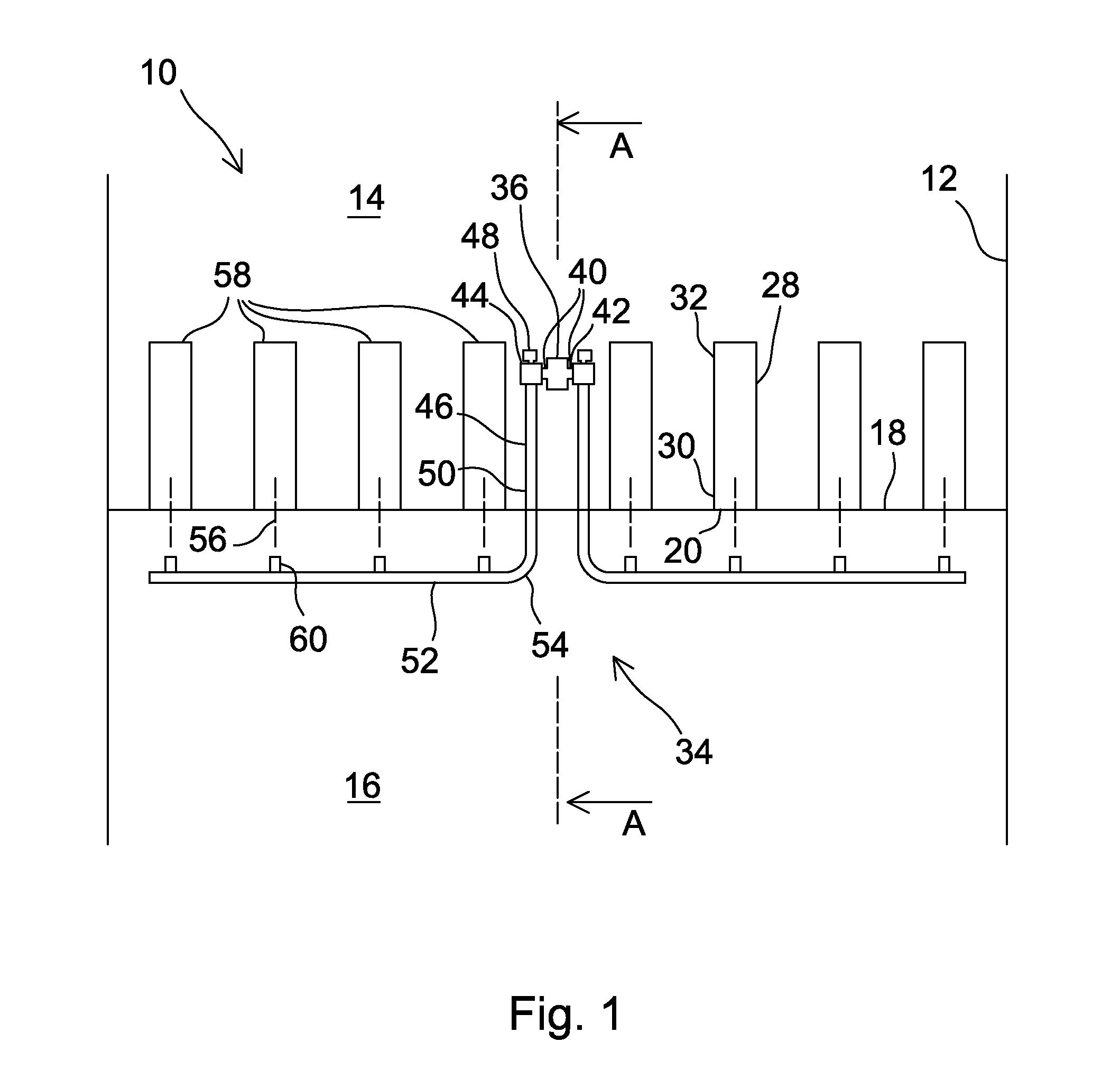
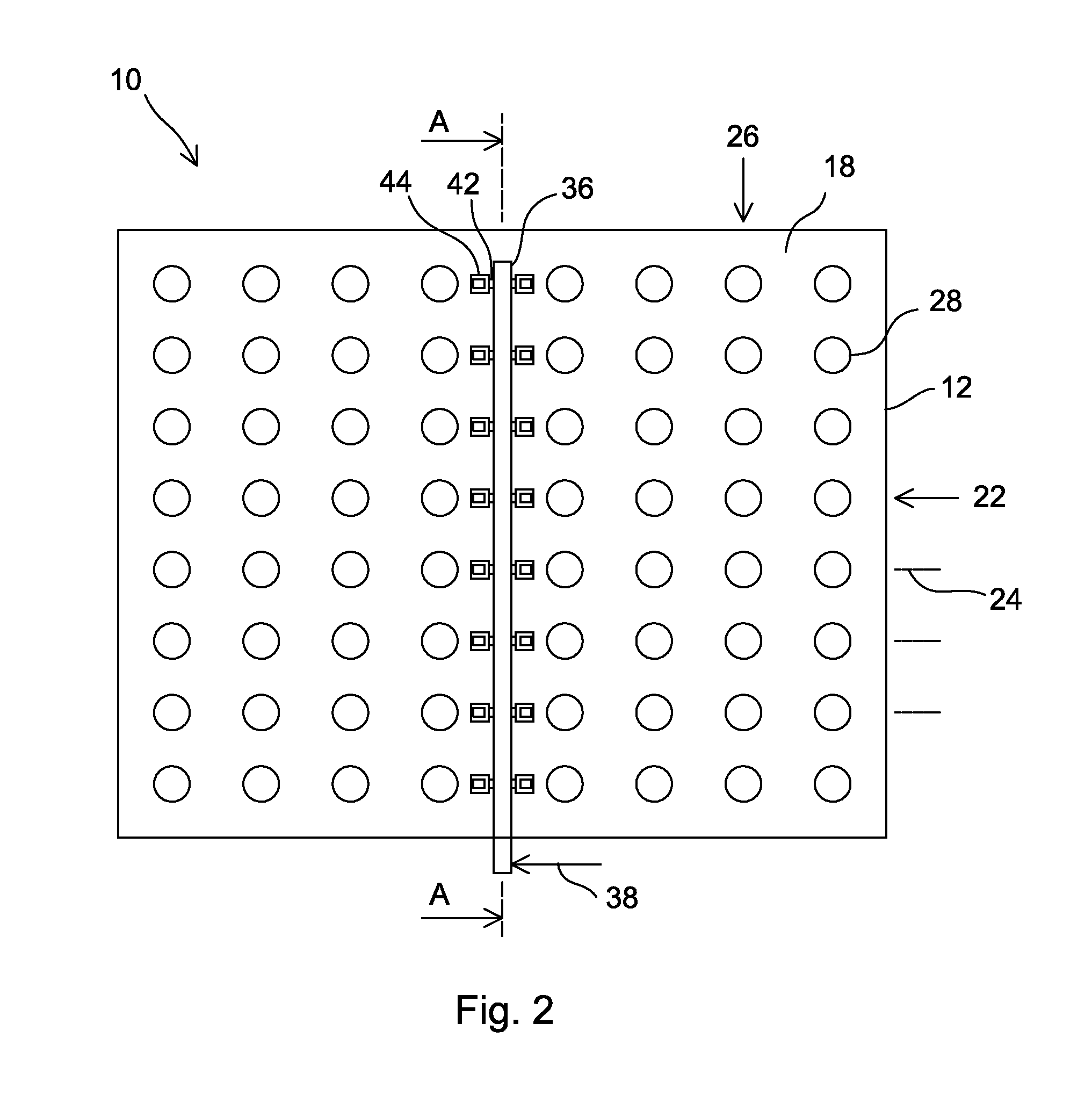
[0027]FIGS. 1, 2, and 3 schematically depict a top view, a side view from the inlet side, and a cross-sectional view along line A-A in FIGS. 1 and 2, respectively, of a pulse cleaning filter system arrangement 10, according to an embodiment of the present invention. The pulse cleaning filter system arrangement 10 can be utilized, for example, for separating harmful particulates from ambient air for a gas turbine by forcing the ambient air through the filter system.
[0028]The pulse cleaning filter system arrangement 10 comprises a housing 12 with an inlet side 14 and an outlet side 16, separated by a vertically arranged planar tubesheet 18. The tubesheet 18 comprises multiple tubesheet openings 20 arranged in a square array of horizontal rows 22, at multiple vertical levels 24, and vertical columns 26. Each of the tubesheet openings 20 is associated with a cylindrical filter cartridge 28 having an open end 30 sealed around the perimeter of the tubesheet opening 20 and a closed end 32 at the inlet side 14 of the housing 12.
[0029]The arrangement 10 comprises a reverse pulse cleaning system 34 for removing collected particles from the filter cartridges 28. The reverse pulse cleaning system 34 comprises a vertical compressed gas header 36 arranged between two vertical columns 26 of filter cartridges 28, at the inlet side 14 of the housing 12. When in operation, the gas header 36 comprises air or other suitable pulse gas, such as flue gas, at a desired pressure, such as about two to about eight atmospheres. The pressure is advantageously maintained by a conventional gas supply 38.
[0030]Pairs 40 of compressed gas outlet stub pipes 42, one on top of the other, extend horizontally from the header 36 to opposite directions at each vertical level 24 of the rows 22 of tubesheet openings 20. Each stub pipe 42 is connected with a right angle pulse valve 44 to a pulse manifold pipe 46 so as to allow filter cleaning gas pulses through the pulse manifold pipes 46 to the filter cartridges 28. The pulse valves 44 are advantageously equipped with quick acting solenoid valves 48 to enable generating gas pulses of a predetermined duration, such as from 0.05 seconds to 0.5 seconds, from the gas header 36 to the respective pulse manifold pipe 46. The gas in the gas pulses is preferably air, but, in some applications, it can also be another gas, such as flue gas. The quick acting solenoid valves 48 are preferably integral to the right angle pulse valves 44, but, in some applications, they can be remote from the pulse valves 44 and connected by tubing.
[0031]Each pulse manifold pipe 46 consists of a horizontal first straight portion 50 extending directly to the tubesheet 18, and, through the tubesheet 18, to the outlet side 16 of the housing 12. The first straight portion 50 is connected to a second straight portion 52 by a sole ninety degree bend 54 at the outlet side 16 of the housing 12. The first straight portion 50 and the second straight portion 52 are thus on a single plane. The second straight portion 52 extends horizontally at the outlet side 16 of the housing 12, parallel with the tubesheet 18.
[0032]The second straight portion 52 of each of the pulse manifold pipes 46 crosses with the central axes 56 of a set 58 of at least four filter cartridges 28 associated with tubesheet openings 20 in one of the horizontal rows 22 of tubesheet openings 20. A gas pulse nozzle 60 is arranged at each crossing of the second straight portion 52 with the central axis 56 of a filter cartridge 28, so that the main injection direction of the nozzle 60 is along the central axis 56 of the filter cartridge 28. Thus, the gas pulses are directed to the filter cartridges 28 in a direction opposite to the normal flow of the ambient air. The gas pulses dislodge particulates from the filter cartridges 28, whereby the dislodged particles reduce the flow resistance of the filter system. Cleaning of all filter cartridges 28 of the filter system is usually performed according to a predetermined sequence while the gas turbine is operating.
[0033]The gas pulse nozzles 60 can be of any suitable type, depending, for example, on the type of the filter cartridges 28. According to a preferred embodiment of the present invention, the nozzles 60 are connected directly to the second straight portion 52. The outlet ends of the gas pulse nozzles 60 are at a suitable distance from the tubesheet 18, such as about 15 to about 50 centimeters.
[0034]FIGS. 1 to 3 show a pulse cleaning filter system arrangement 10 with eight rows and eight columns of tubesheet openings 20, or filter cartridges, wherein each pulse valve provides cleaning gas pulses to four filter cartridges 28. In practice, the number of rows in a filter system can be less than or greater than eight, and the number of columns served by a single gas header 36 can be greater than eight, such as ten or twelve. It is also possible that a pulse cleaning filter system arrangement 10 comprises multiple compressed gas headers 36 arranged side-by-side, so as to enable a large filter system with a large number, such as twenty or even more, of columns of the filter cartridges 28.
[0035]While the invention has been described herein by way of examples in connection with what are, at present, considered to be the most preferred embodiments, it is to be understood that the invention is not limited to the disclosed embodiments, but is intended to cover various combinations or modifications of its features, and several other applications included within the scope of the invention, as defined in the appended claims. The details mentioned in connection with any embodiment above may be used in connection with another embodiment when such a combination is technically feasible.

PUM

PropertyMeasurementUnit
Length0.75m
Length1.0m
Length0.91m

Description & Claims & Application Information

We can also present the details of the Description, Claims and Application information to help users get a comprehensive understanding of the technical details of the patent, such as background art, summary of invention, brief description of drawings, description of embodiments, and other original content. On the other hand, users can also determine the specific scope of protection of the technology through the list of claims; as well as understand the changes in the life cycle of the technology with the presentation of the patent timeline. Login to view more.

Similar technology patents

Microarray system

ActiveUS20090280997A1high capacityprevents total solubilization
Owner:AKONNI BIOSYSTEMS INC

Classification and recommendation of technical efficacy words

  • high capacity

Method of fabricating semiconductor stack package

InactiveUS20120077314A1high capacitysmall volume
Owner:SAMSUNG ELECTRONICS CO LTD

Piezoelectric fluid pump

InactiveUS20050244288A1high capacity
Owner:T BANK N A

Venting system for minimizing condensation in a lighting assembly

ActiveUS20060150817A1reduce condensationhigh capacity
Owner:WL GORE & ASSOC INC

Elevated bus rapid transit system

InactiveUS20060196385A1less trip timehigh capacity
Owner:STROMBERG DALE MARIE
Why Eureka
Try Eureka