Power storage device and electronic device

Active Publication Date: 2016-12-22
SEMICON ENERGY LAB CO LTD
View PDF3 Cites 21 Cited by
  • Summary
  • Abstract
  • Description
  • Claims
  • Application Information

AI Technical Summary

Benefits of technology

[0005]An object of one embodiment of the present invention is to provide a power storage device with high capacity per unit volume. Another object of one embodiment of the present invention is to provide a flexible power storage device with a novel structure. Another object of one embodiment of

Problems solved by technology

In particular, an exterior film of a power storage device that has flexibility and is intended for us

Method used


Image

  • Power storage device and electronic device
  • Power storage device and electronic device
  • Power storage device and electronic device

Examples


Example

Embodiment 1

[0053]In this embodiment, a power storage device 110 of one embodiment of the present invention and a manufacturing method thereof are described.

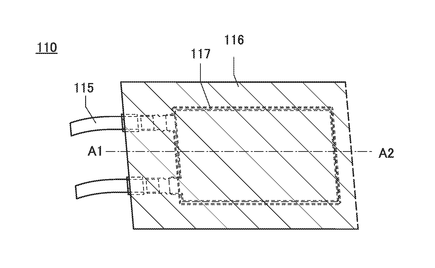
[0054]FIGS. 1A to 1C illustrate the power storage device 110. The power storage device 110 in FIG. 1A includes an inner structure 117 surrounded by an exterior body 116. The inner structure 117 includes an electrode and a separator, and the electrode is electrically connected to a lead electrode 115.

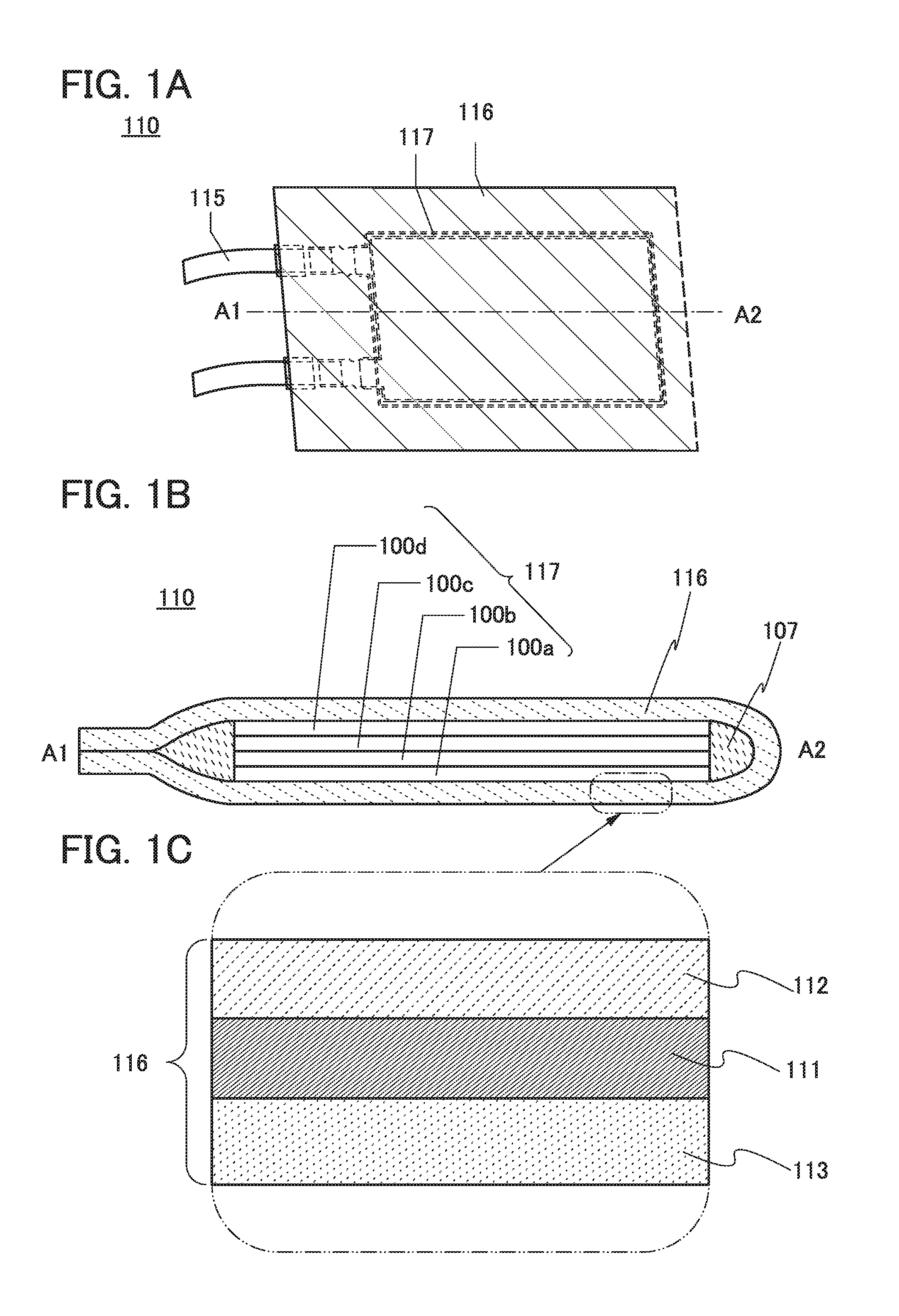
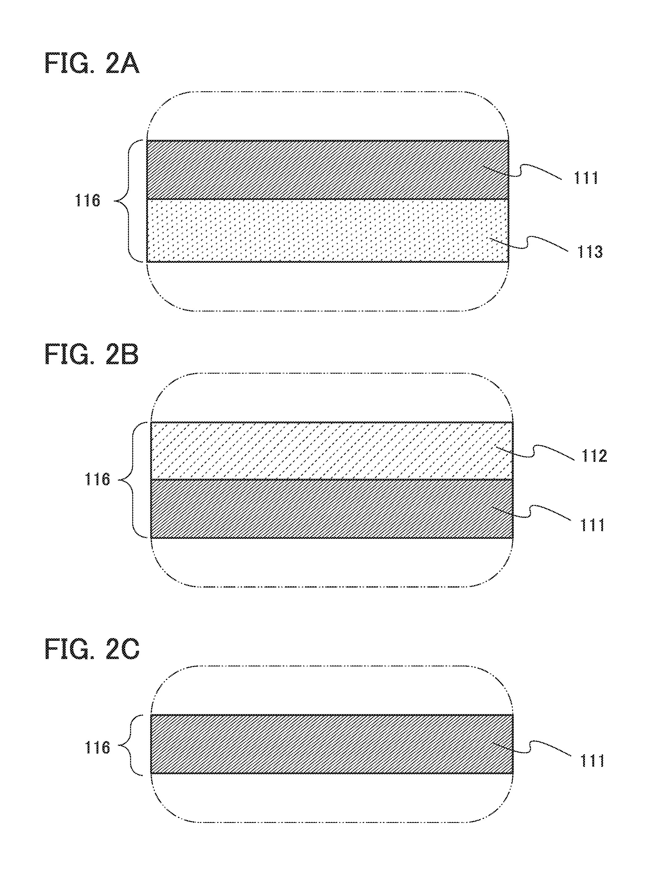
[0055]FIG. 1B is a cross-sectional view of the power storage device 110 taken along line A1-A2 in FIG. 1A. FIG. 1C is an enlarged view of the exterior body 116.

[0056]As illustrated in FIG. 1B, the power storage device 110 has a structure in which the inner structure 117 and an electrolytic solution 107 are surrounded by the exterior body 116. The inner structure 117 includes a first stack100a, a second stack 100b, a third stack 100c, and a fourth stack 100d. Note that the number of stacks included in the power storage device 110 of t...

Example

Embodiment 2

[0160]In this embodiment, structures of a storage battery of one embodiment of the present invention are described with reference to FIGS. 10A and 10B, FIG. 11, FIG. 12, FIGS. 13A to 13C, and FIGS. 14A to 14E.

[0161]An example of a laminated storage battery will be described with reference to FIG. 10A. When a flexible laminated storage battery is used in an electronic device at least part of which is flexible, the storage battery can be bent as the electronic device is bent.

[0162]A laminated storage battery 500 illustrated in FIG. 10A includes a positive electrode 503 including a positive electrode current collector 501 and a positive electrode active material layer 502, a negative electrode 506 including a negative electrode current collector 504 and a negative electrode active material layer 505, a separator 507, an electrolytic solution 508, and an exterior body 509. The separator 507 is provided between the positive electrode 503 and the negative electrode 506 in the ...

Example

Embodiment 3

[0209]In this embodiment, an example of an electronic device including the power storage device described in Embodiment 1 or the like will be described.

[0210]FIG. 19 illustrates an example of an armband electronic device including a flexible power storage device. An armband device 7300 illustrated in FIG. 19 can be worn on an arm 7301 and includes a display portion having a curved surface and a bendable power storage device.

[0211]Note that in the display portion, a display element, a display device which is a device including a display element, a light-emitting element, and a light-emitting device which is a device including a light-emitting element can employ a variety of modes or can include a variety of elements. The display element, the display device, the light-emitting element, or the light-emitting device includes at least one of an electroluminescent (EL) element (e.g., an EL element including organic and inorganic materials, an organic EL element, or an inorgani...


PUM


Abstract

A power storage device with high capacity per unit volume, a flexible power storage device with a novel structure, a repeatedly bendable power storage device, a highly reliable power storage device, or a long-life power storage device is provided. The power storage device includes an inner structure and an exterior body surrounding the inner structure. The inner structure includes a positive electrode and a negative electrode. The exterior body includes a first film containing titanium and one or more elements selected from niobium, tantalum, vanadium, zirconium, and hafnium. It is preferable that the first film further contain one or more elements selected from molybdenum, chromium, and aluminum.

Description

TECHNICAL FIELD[0001]The present invention relates to an object, a method, or a manufacturing method. The present invention relates to a process, a machine, manufacture, or a composition of matter. One embodiment of the present invention particularly relates to a semiconductor device, a display device, a light-emitting device, a power storage device, an imaging device, a driving method thereof, or a manufacturing method thereof. One embodiment of the present invention particularly relates to a power storage device and a method for manufacturing a power storage device.BACKGROUND ART[0002]In recent years, wearable devices have been under active development. Since wearable devices are worn on one's body, it is preferable that they have shapes curved along a curved surface of the body or they be curved according to the movement of the body. Therefore, it is preferable that a power storage device used in a wearable device also have flexibility like displays and other housings.[0003]Furth...

Claims


Application Information

Patent Timeline
IPC IPC(8): H01M2/02H01M50/105H01M50/117H01M50/133H01M50/136H01M50/178H01M50/55H01M50/557
CPCH01M2/026H01M2/0285H01M2/0287H01M2220/30H01M2/0275H01M2002/0297H01M2/028H01M10/0436H01M10/0459Y02E60/10H01M50/557H01M50/124Y02P70/50H01M50/105H01M50/133H01M50/136H01M50/117H01M50/55H01M50/178
Inventor NODA, KOSEI
Owner SEMICON ENERGY LAB CO LTD
Why Eureka
Try Eureka