
Control device for a regenerative braking system of a vehicle, and method for operating a regenerative braking system of a vehicle

a regenerative braking and control device technology, applied in the direction of braking systems, instruments, analogue processes for specific applications, etc., can solve the problems of imperceptible torque or a high vehicle deceleration, and the maximum impartable can-engine braking torque is reduced, and the effect of effective operation

Active Publication Date: 2015-08-27
ROBERT BOSCH GMBH
View PDF5 Cites 4 Cited by
  • Summary
  • Abstract
  • Description
  • Claims
  • Application Information

AI Technical Summary

Benefits of technology

The present invention improves the use of the deceleration potential of electric motors in braking systems by better utilizing the additional regenerative deceleration potential. This is achieved by adding a non-compensated or blended deceleration component, which improves the efficiency of braking without affecting the driver's sensory experience. The invention also helps reduce fuel consumption and pollutant emissions by controlling the engine in generator mode. The control device can define the setpoint engine braking torque variable based on the vehicle's speed and battery charge level, and can control the additional friction brakes with the aid of an additional control signal. This ensures better braking comfort and reduces the need for costly hydraulic components. The control device can also limit the increase in the setpoint engine braking torque to prevent discomfort for the driver. Overall, the invention improves the efficiency and performance of electric vehicles' braking system.

Problems solved by technology

Moreover, the non-compensated or blended elimination of the additional braking torque is imperceptible or virtually imperceptible to the driver.
This is due, in particular, to the fact that fluctuations in deceleration during a high requested setpoint overall braking torque or a high vehicle deceleration are significantly more difficult for a driver to perceive.

Method used


Image

  • Control device for a regenerative braking system of a vehicle, and method for operating a regenerative braking system of a vehicle
  • Control device for a regenerative braking system of a vehicle, and method for operating a regenerative braking system of a vehicle
  • Control device for a regenerative braking system of a vehicle, and method for operating a regenerative braking system of a vehicle

Examples


Embodiment Construction

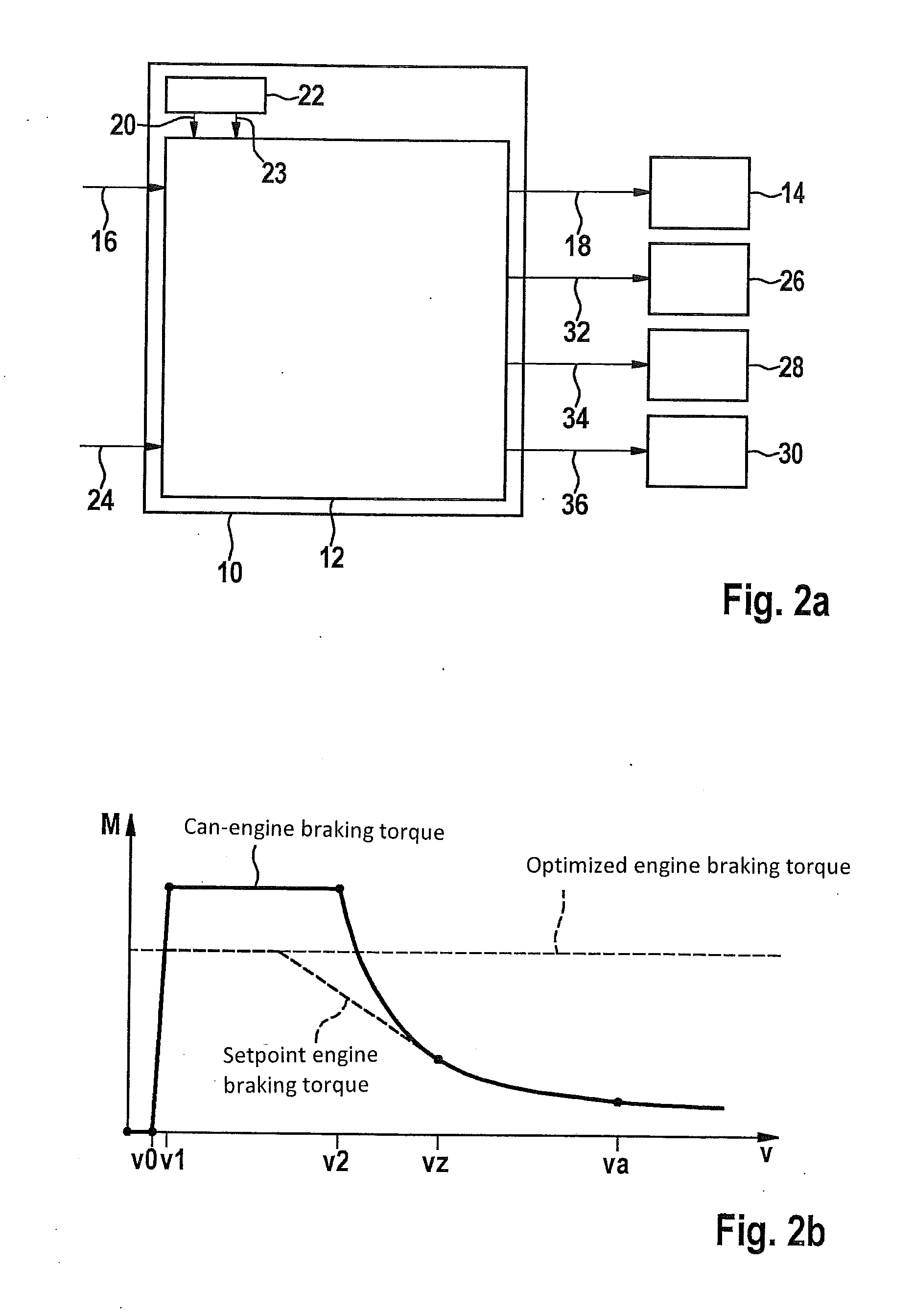
[0023]FIGS. 2a and 2b schematically show a representation of one specific embodiment of the control device and a coordinate system for illustrating the functionality thereof.

[0024]Control device 10 schematically depicted in FIG. 2a includes an engine control device 12, with the aid of which at least one setpoint engine braking torque variable with respect to at least one setpoint engine braking torque to be exerted of at least one electric motor 14 of the braking system usable in generator mode may be defined. Defining the setpoint engine braking torque variable may be carried out taking into consideration at least one setpoint overall braking torque variable 16 provided by at least one on-board sensor and / or by one on-board automatic vehicle control, with respect to a predefined setpoint overall braking torque. In addition, at least one (not depicted) actual friction braking torque variable with respect to at least one imparted or impartable (overall or individual) actual friction ...


PUM


Abstract

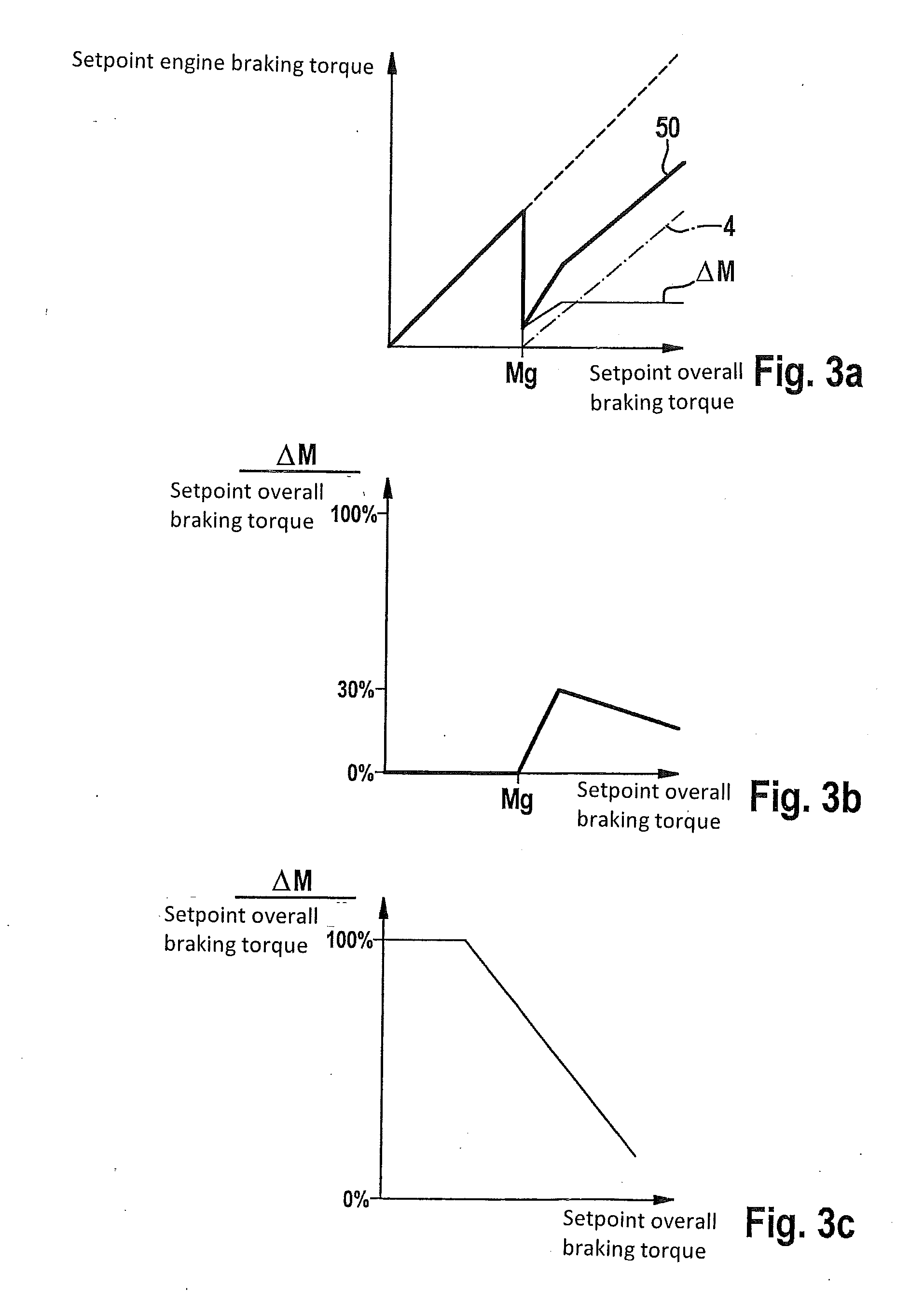
A control device for a vehicle regenerative braking system, having an engine control device, with which a setpoint engine braking torque variable for a setpoint engine braking torque to be imparted by an electric motor, useable in generator mode, is defineable, considering a setpoint overall braking torque variable for a predefined setpoint overall braking torque, and considering an actual friction braking torque variable for an imparted / impartable actual friction braking torque of at least one additional friction brake, wherein if the setpoint variable is below a threshold, the setpoint variable is defineable according to a difference between the setpoint overall braking torque to be imparted and the imparted / impartable braking torque, and if the setpoint variable is above the threshold, the setpoint variable is defineable according to a sum of a predefined additional braking torque and the difference. Also described are a regenerative braking system and method.

Description

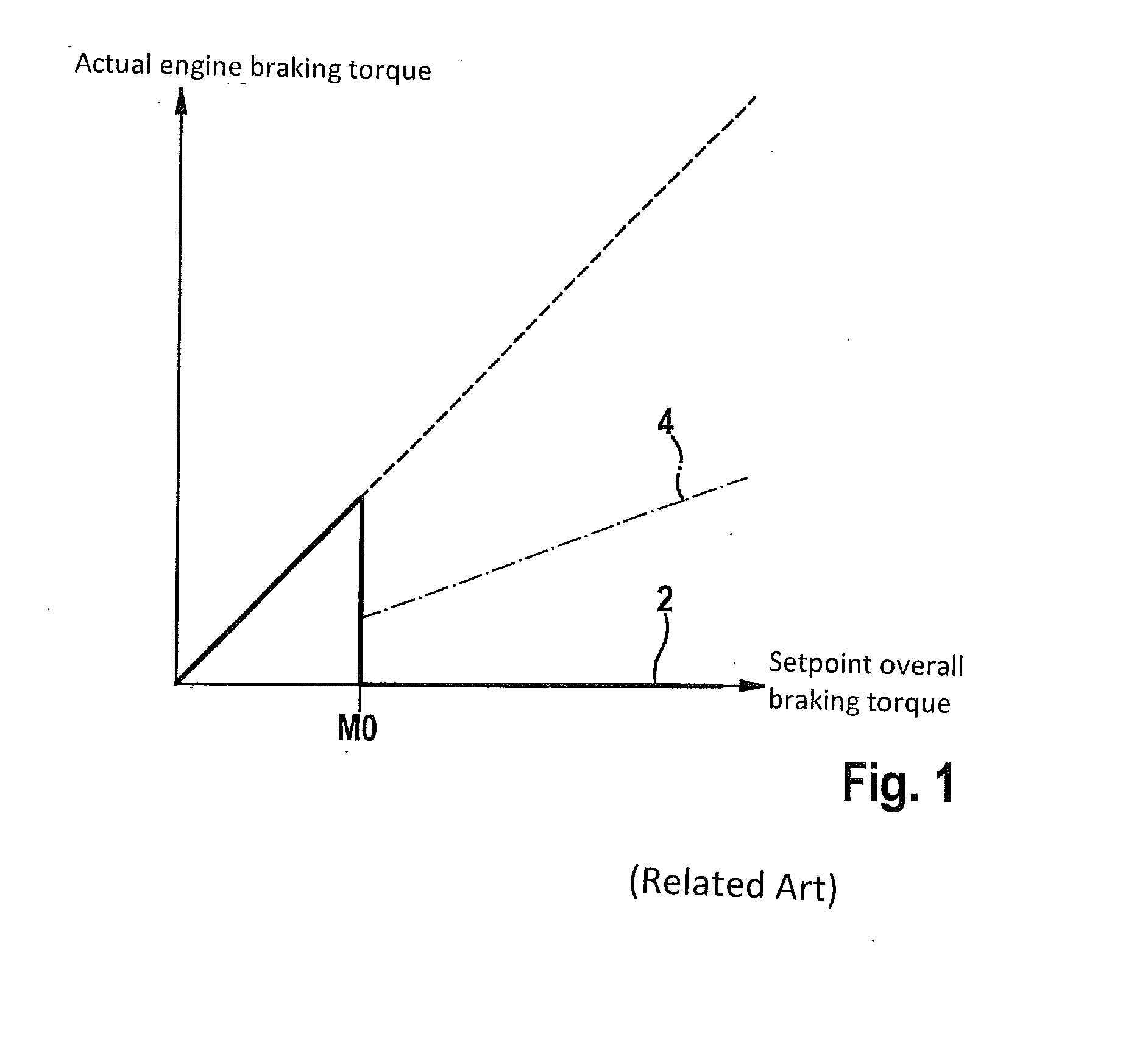
FIELD OF THE INVENTION[0001]The present invention relates to a control device for a regenerative braking system of a vehicle. The present invention also relates to a regenerative braking system for a vehicle. In addition, the present invention relates to a method for operating a regenerative braking system of a vehicle.BACKGROUND INFORMATION[0002]FIG. 1 shows a coordinate system for illustrating a conventional method for controlling a braking system. The conventional method for controlling the braking system is discussed, for example, in DE 10 2008 004 201 A1.[0003]The x-axis of the coordinate system of FIG. 1 indicates a setpoint overall braking torque Mges-soll requested by a driver of a vehicle equipped with the relevant braking system. The requested setpoint overall braking torque Mges-soll may also be described as a driver braking intention and may be ascertained, for example, via an adjustment travel of a brake actuating element (pedal travel). An actual engine braking torque ...

Claims


Application Information

Patent Timeline
Patent Type & Authority Applications(United States)
IPC IPC(8): B60L7/18B60W10/188B60W10/08
CPCB60L7/18B60W10/08B60W2510/18B60W2510/083B60W10/188B60W10/06B60W10/184B60W30/18127B60T2270/604B60W2720/106B60W2710/0666B60T1/10F16D61/00
Inventor MAUCHER, THORSTENBODMANN, JOCHENBAUER, GOTTFRIEDSTRENGERT, STEFAN
Owner ROBERT BOSCH GMBH
Learn More