Wall construction method using injected urethane foam between the wall and autoclaved concrete (AAC) blocks

a technology of urethane foam and wall, which is applied in the direction of walls, constructions, building components, etc., can solve the problems of limiting the use of construction systems, limiting the use of construction methods, and limiting so as to limit the water and/or vapor infiltration

Inactive Publication Date: 2015-08-27
BRETON SYST LLC
View PDF43 Cites 15 Cited by
  • Summary
  • Abstract
  • Description
  • Claims
  • Application Information

AI Technical Summary

Benefits of technology

[0042]It will be understood by those skilled in the art that junctions between dissimilar materials (and sometime similar materials) and any protrusions through the finished walls (e.g., doors, windows, piping, ducts, structural members, etc.) may benefit from optional inclusion of one or more suitable flashings, counter flashings, drip caps, flexible sealants, caulks (e.g., siliconized caulks), mortars, adhesives, and the like, to limit water and / or vapor infiltration and / or to provide stability.

Problems solved by technology

Generally, these construction systems, while widely used, are known to have various limitations, including, allowing moisture penetration, thermal bridging, air infiltration, being subject to decay, mold and mildew, infestation, vulnerability to fire, and / or time consuming and labor intensive or expensive construction methods.
While existing AAC construction methods can ameliorate some of these limitations seen in conventional building materials and construction methods, the construction field generally still searches for answers to a number of persistent limitations.
Nevertheless, what is needed are wall construction systems and materials suitable for residential, commercial, and other construction projects that substantially ameliorate at least some of the disadvantages of existing conventional and / or AAC construction techniques such as reducing labor requirements during construction and / or other installation requirements.

Method used


Image

  • Wall construction method using injected urethane foam between the wall and autoclaved concrete (AAC) blocks
  • Wall construction method using injected urethane foam between the wall and autoclaved concrete (AAC) blocks
  • Wall construction method using injected urethane foam between the wall and autoclaved concrete (AAC) blocks

Examples


Embodiment Construction

[0055]While several variations of the present invention have been illustrated by way of example in preferred or particular embodiments, it is apparent that further embodiments could be developed within the spirit and scope of the present invention, or the inventive concept thereof.

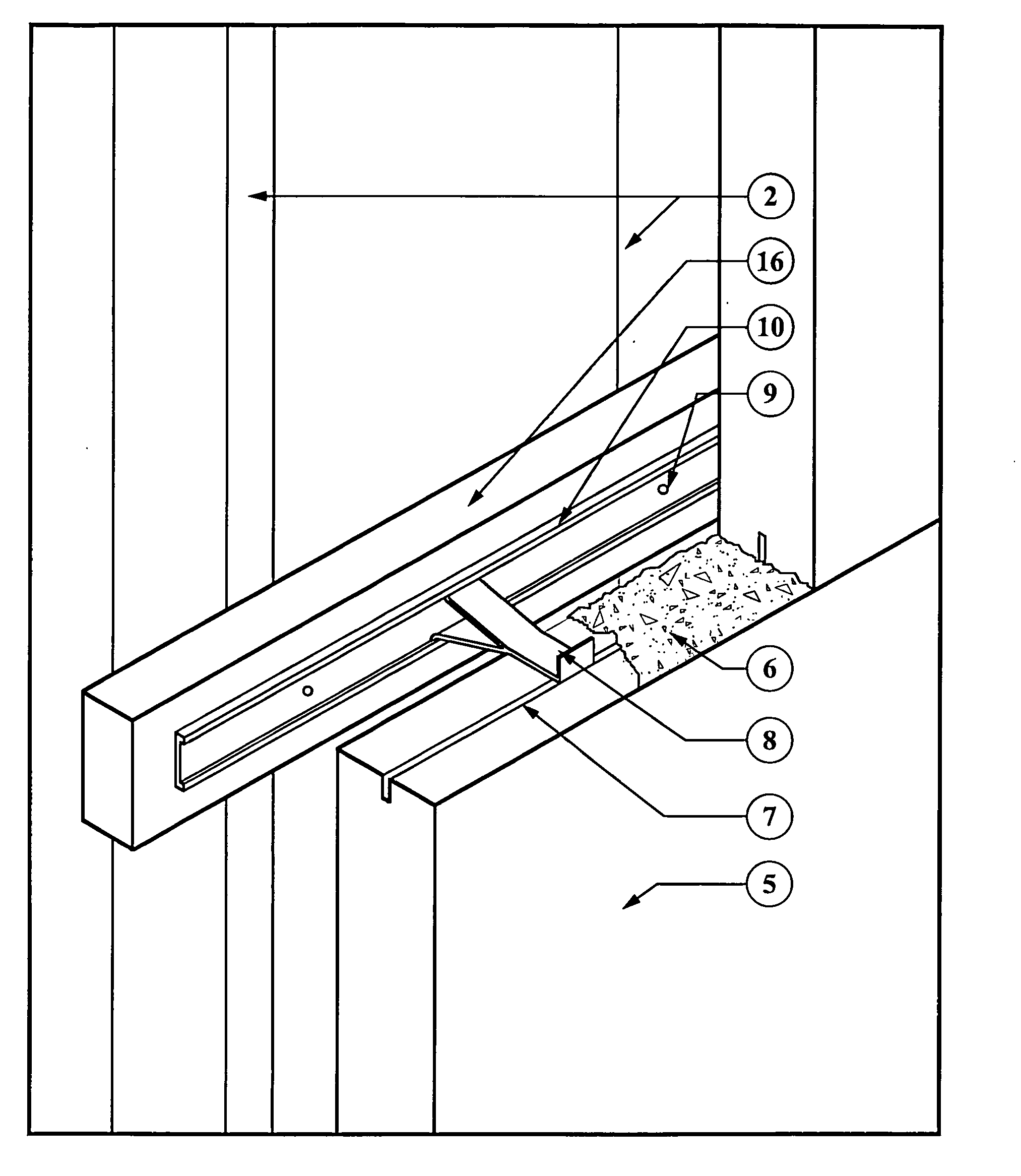
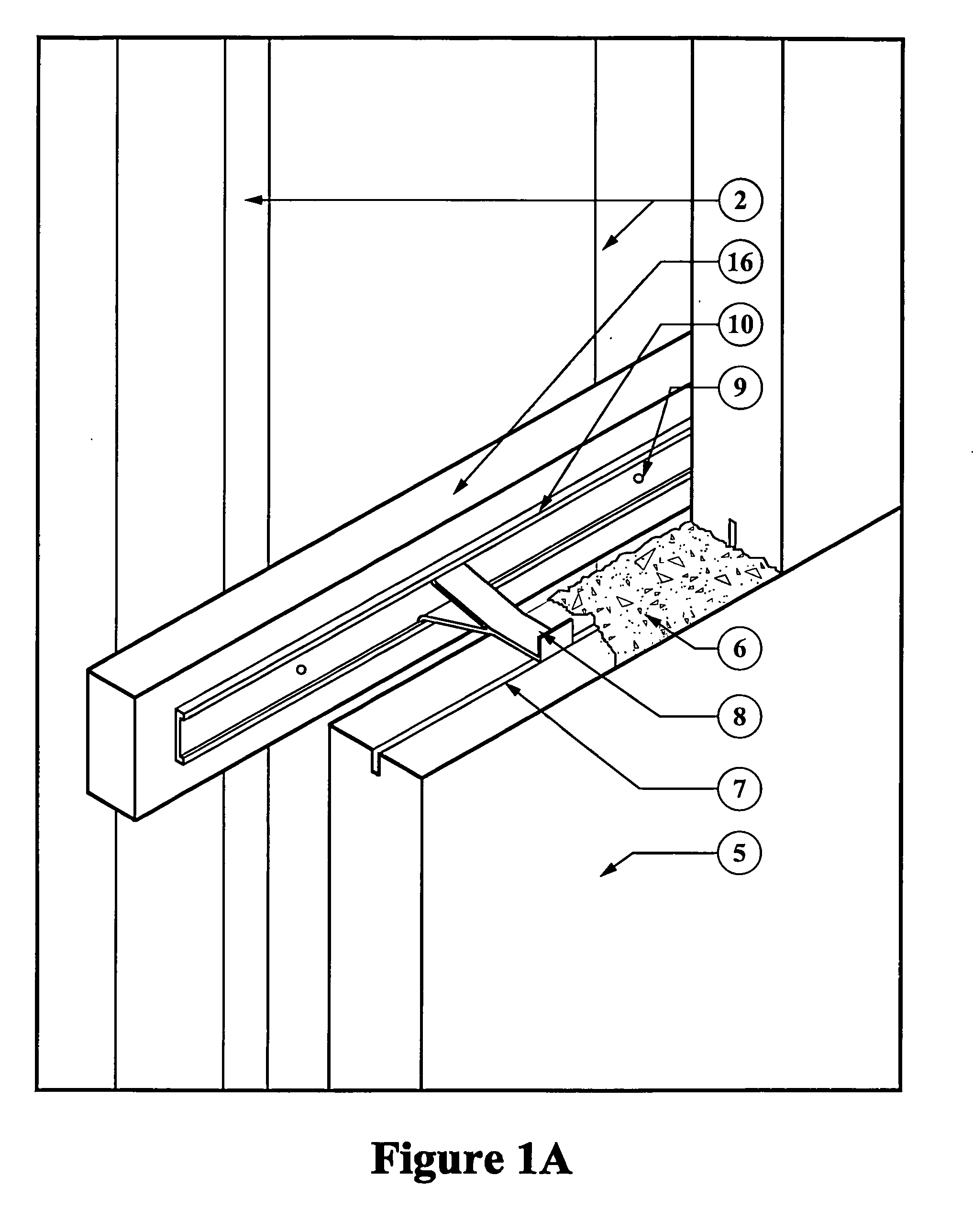
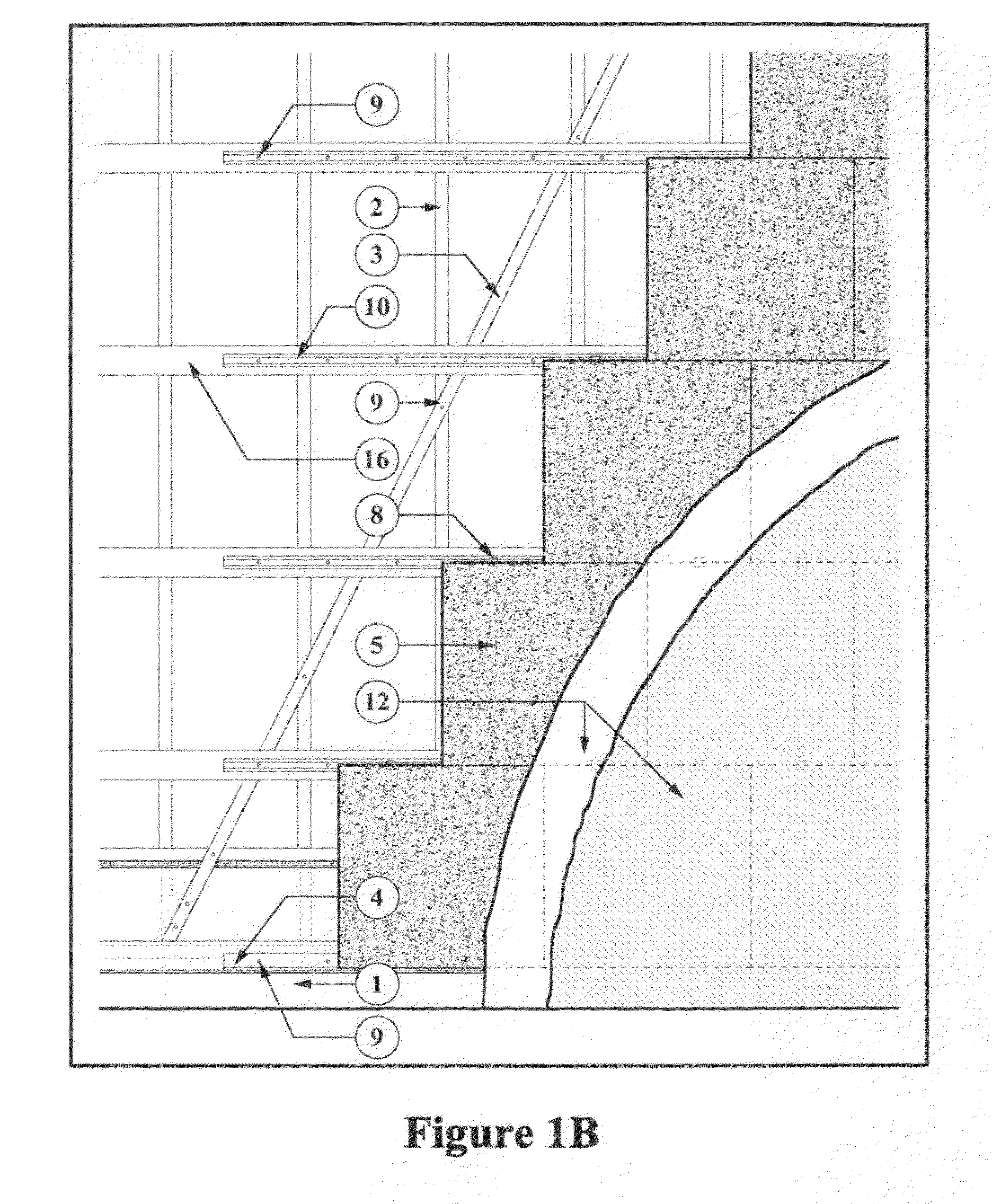
[0056]The invention comprises a novel wall system for residential and light commercial construction that incorporates lightweight construction material units such as AAC blocks. This wall system comprises an exterior wall composed of AAC blocks married to an interior wood or metal load-bearing (structural) framing. The AAC blocks would be anchored to the framing using novel construction clips. Furthermore, a cavity or space between the framing and the interior surface of the exterior wall comprising AAC blocks is injected with structural polyurethane foam insulation to adhere the framing and the walls together and to provide insulation, air-sealing, and vapor-proofing. The exterior of the AAC walls further...


PUM


Abstract

The present invention provides novel wall construction systems and materials for residential and commercial construction that incorporate grooved lightweight building material units (e.g., blocks, panels, and the like), a plurality of connection devices, a track system, and (injected) polyurethane structural foam. The wall construction system comprises building material units married to a building frame with a plurality of connection devices (e.g., clip fasteners) slidingly retained in a track system that is attached to the building's structural (e.g., load-bearing) framing. The building material units are joined to each other with a suitable binding agent. The cavity between the frame and the building material units is injected with an insulating structural polyurethane foam. The exterior of the wall is finished with a waterproof applied finish such as cementitious stucco. The interior of the wall is amenable to standard finish options.

Description

CLAIM OF PRIORITY[0001]This patent application makes reference to, claims priority to and claims benefit from U.S. Provisional Patent Application Ser. No. 61 / 966,518 filed on 25 Feb. 2014. The above stated application is hereby incorporated herein by reference in its entirety.FIELD OF THE INVENTION[0002]The present invention provides novel wall construction systems and materials for residential and commercial construction that incorporate grooved lightweight building material units (e.g., blocks, panels, and the like), a plurality of connection devices, a track system, and (injected) polyurethane structural foam. The wall construction system comprises building material units married to a building frame with a plurality of connection devices (e.g., clip fasteners) slidingly retained in a track system that is attached to the building's structural (e.g., load-bearing) framing. The building material units are joined to each other with a suitable binding agent. The cavity between the fra...

Claims


Application Information

Patent Timeline
Patent Type & Authority Applications(United States)
IPC IPC(8): E04B1/76E04B1/78E04B1/41E04B2/58E04B2/70
CPCE04B1/7604E04B2/58E04B2001/7679E04B1/40E04B1/78E04B2/70E04B1/26E04B1/4178E04B2/707E04B2001/2481E04B2001/2696
Inventor RIEPE, FRANK WARNER
Owner BRETON SYST LLC
Why Eureka
Try Eureka