Container, containing device and method for taking out contained product

a technology of containing devices and containers, applied in the direction of liquid handling, containers preventing decay, instruments, etc., can solve the problems of liquid being taken out, liquid not being sucked to a high level, etc., to achieve accurate quantitative determination, easy operation, and convenient use

Active Publication Date: 2015-08-27
BEIJING RED SEA TECH
View PDF4 Cites 7 Cited by
  • Summary
  • Abstract
  • Description
  • Claims
  • Application Information

AI Technical Summary

Benefits of technology

[0059]Such a taking-out method is easy to operate and easy to use, enables accurate quantitative determination, basically realizes stepless continuous taking-out, can be applied to liquids or pastes with greater viscosity and consistency, and can also be applied to liquids to be taken out in a spray shape.

Problems solved by technology

1. The amount of a liquid taken out by using a pressing pump cannot be controlled precisely. A force generated by downward press of a pressing device is not constant, so the amount of the liquid taken out often can only be measured with the number of presses, and the amount of the liquid taken out cannot be controlled precisely.
2. Viscosity and consistency of the liquid taken out cannot be too high. The pressure drop of the pressing device is big, if viscosity and consistency of the liquid are too high, the liquid cannot be sucked to a high level and cannot be taken out; it is less conducive to further forming spray or foam by the contained product.
3. The manufacturing cost is high. The pressing device has a complex structure, two check valves are generally required, which need to be produced and assembled separately, necessary parts such as container walls are not utilized, and thus the manufacturing cost is high.
4. Continuous taking-out is impossible. The pressing device can only take out a contained product in a limited space near a straw outlet each time, after the contained product in the space is taken out, another contained product can be taken out only after being inhaled from the container below, and thus the liquid can only be taken out in small volume and intermittently, and continuous taking-out is impossible.
In the prior art, it is difficult to take out liquids or pastes with great consistency or viscosity, with the reason that pressure drop of the whole channel in the taking-out process is very great.

Method used


Image

  • Container, containing device and method for taking out contained product
  • Container, containing device and method for taking out contained product
  • Container, containing device and method for taking out contained product

Examples


embodiment 1

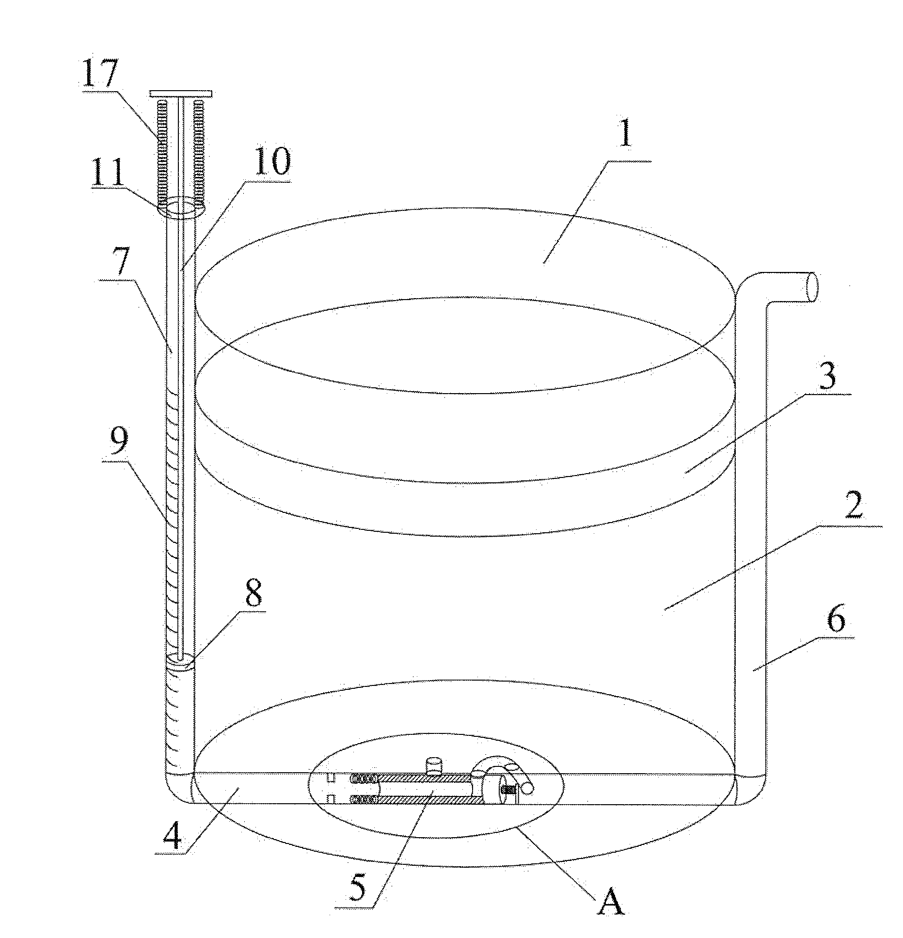
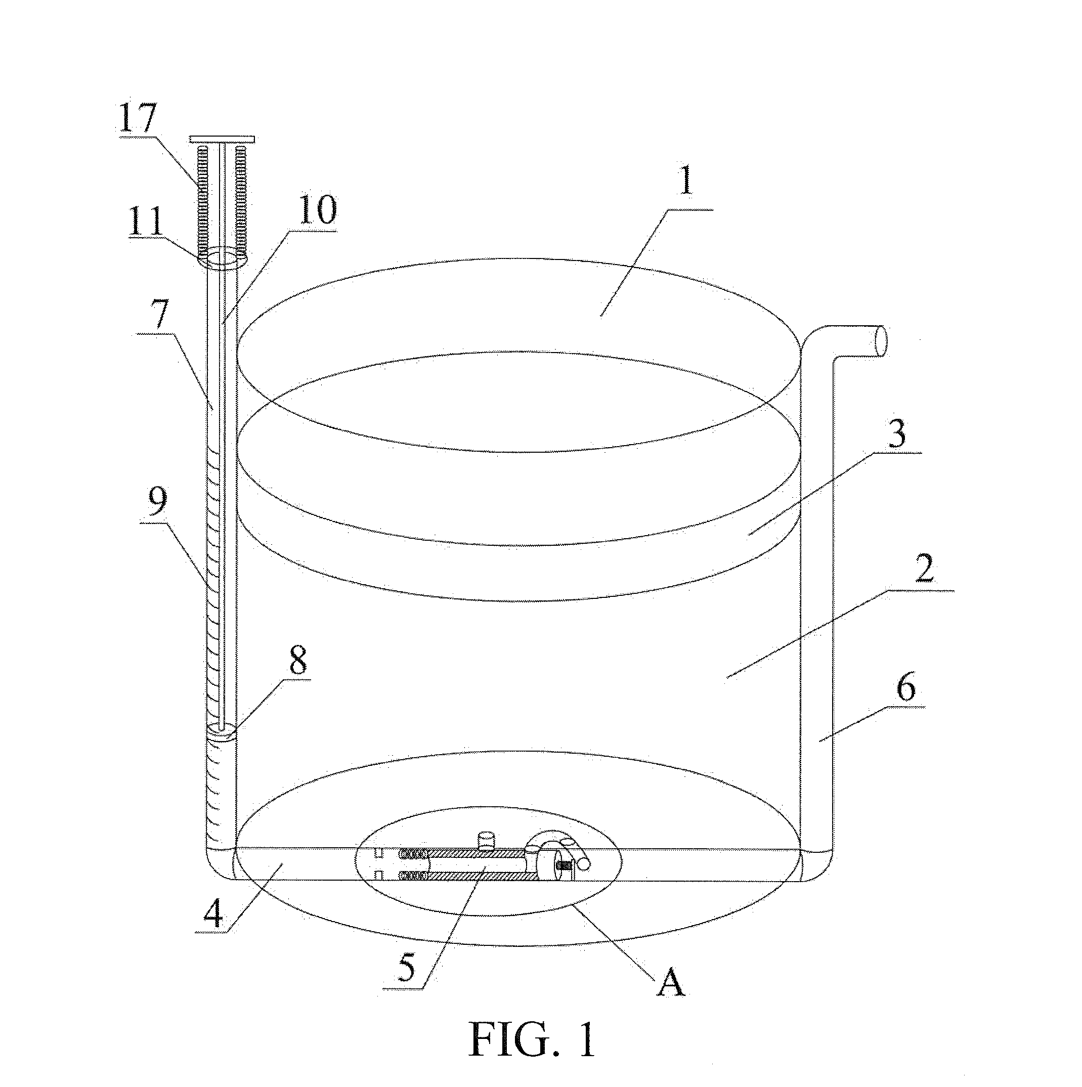
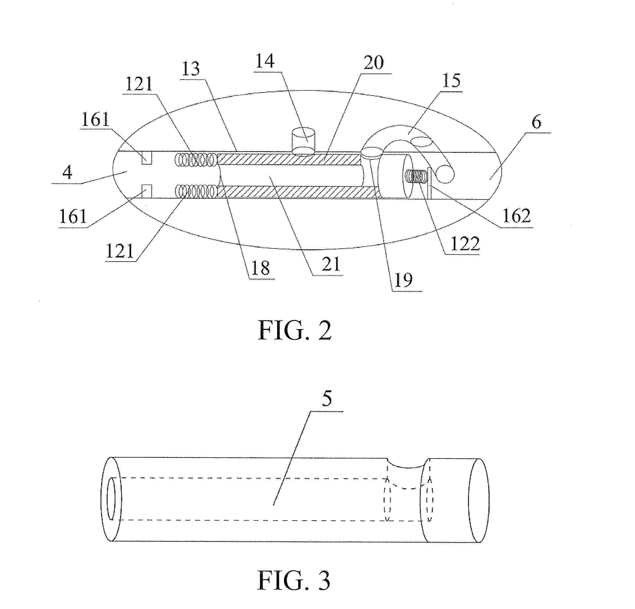
[0069]As shown in FIG. 1, FIG. 2 and FIG. 3, FIG. 1, FIG. 2 and FIG. 3 illustrate a container according to Embodiment 1 of the present invention. The body 1 of the container is cylindrical, containing a liquid product 2, above the liquid product is a piston 3, and the piston 3 can move up and down in the body 1. On walls of the body 1, channels formed by sequential connections between a variable pressure part 7, a pressure transfer channel 4, a control valve 5 and an outflow channel 6 are attached to sidewalls and bottom walls of the body.

[0070]The variable pressure part 7 includes a transparent channel 9 with scales, a piston 8 inside the transparent channel 9 and an operating lever 10 connected to the piston 8 to extend outside the transparent channel 9. The operating lever 10 can drive the piston 8 to move up and down along the transparent channel 9, and a ring 11 blocks the piston 8 from moving up and falling off. The transparent channel 9 of the variable pressure part 7 is in a...

embodiment 2

[0081]As shown in FIG. 4 and FIG. 5, FIG. 4 and FIG. 5 illustrate a container according to Embodiment 2. The container includes a container body 1, an upper portion of the container body 1 has a filling port, and after the contained product 2 is filled, the filling port is sealed with the check valve 3. The check valve 3 only allows gas to enter into the container body 1.

[0082]The middle position of the container body 1 is installed with the pressure transfer channel 4 extending into its interior. The container body 1 and the pressure transfer channel 4 are airtight. The pressure transfer channel 4, at an outer end of the container body 1 through a thread 15, connects an airbag 7 having capability to recover after squeeze, and, at an inner end, communicates with the control valve 5. The pressure transfer channel 4 has a piston 10 therein, and the piston 10 separates the gas in the airbag 7 from the contained product 2 in the pressure transfer channel 4, and indicates the moving posi...

embodiment 3

[0094]As shown in FIG. 6 and FIG. 7, FIG. 6 and FIG. 7 illustrate a container according to Embodiment 3. A container body of the container includes two parts: a space 1 and a space 2, which are respectively filled with a contained product 17 and a contained product 16. After being filled with the contained products, filling ports of the space 1 and the space 2 are respectively blocked with check valves 3, and the check valves 3 only allow gas to enter into the container body 1, to prevent the contained product 16 and the contained product 17 from volatilizing outwards.

[0095]A variable pressure part 7 is located at the top of the container, including a piston 8, a pressurized bar 9 and a cylindrical object 22 with scales. The variable pressure part 7 is in communication with a pressure transfer channel 4, and the pressure transfer channel 4 is in communication with one end of a control valve 5. Good airtightness exists between the variable pressure part 7, the pressure transfer chann...


PUM


Abstract

A container and method for taking out contained product. The container comprises a container body, a pressure transfer channel, a control valve, a liquid taking channel and an outflow channel, the control valve contains a moving part. The moving part is at different positions along with variation of pressure applied to a variable pressure part, and connection and disconnection of the channels which between the pressure transfer channel and the outflow channel and between the liquid taking channel and the pressure transfer channel are determined by three positions of the moving part. The container can quantitatively take out contained product, is simple in structure and avoid the product to be oxidized or polluted.

Description

BACKGROUND[0001]1. Technical Field[0002]The present invention relates to a container, a containing device and a method for taking out a contained product, and in particular to a container and a containing device from which a contained product is taken out conveniently, quickly and quantitatively, and a method for taking out a contained product in a container.[0003]2. Related Art[0004]In daily life, people may use many liquids or pastes, such as washing liquids, sterilizing liquids, shampoos, body washes, toothpastes, soy, vinegar, salad dressing, honey, edible oil and liquid medicines. Containers containing these liquids or pastes are mostly disposable articles, which often only pay attention to labeling and beautiful effects but pay little attention to how to conveniently take out the contained products, and an inverted toppling method and a method for taking out by a pressing pump are commonly used. Problems existing in the inverted toppling method have been fully described in oth...

Claims


Application Information

Patent Timeline
Patent Type & Authority Applications(United States)
IPC IPC(8): F16K15/02B65D25/38
CPCB65D25/38F16K15/02B65D81/24B65D81/245B65D83/00F16K11/0716F16K17/0473G01F11/16
Inventor CHEN, ZENGXINLUO, SHUMIN
Owner BEIJING RED SEA TECH
Why Eureka
Try Eureka