Method and apparatus control and adjustment of pulse optimization of a magnetic resonance system

a technology of magnetic resonance system and optimization method, which is applied in the direction of reradiation, measurement using nmr, instruments, etc., can solve the problems of high slew rate, high energy consumption, and more exact requirements for gradient coils and other hardware, so as to facilitate real-time use and accelerate calculation and implementation of pulse sequences.

Active Publication Date: 2015-08-27
SIEMENS HEALTHCARE GMBH
View PDF12 Cites 12 Cited by
  • Summary
  • Abstract
  • Description
  • Claims
  • Application Information

AI Technical Summary

Benefits of technology

[0013]An object of the present invention is to provide a solution to the problem of scans being aborted when pulse optimization methods are used as real-time applications.
[0024]In this case, if the time available for pulse optimization is insufficient, the pulse optimization step is bypassed. The pulse sequence optimization device, i.e. the pulse shape optimization unit, can therefore be switched “passive” if reducing the gradient grid density does not deliver the required computing time saving. In this case, all the commands are forwarded directly to the MR scanner without being optimized or modified by the pulse shape optimization unit. As a result, the computing time of the pulse sequence optimization unit falls to zero so that a scan abort can be prevented.
[0029]For example, the calculation of the optimized gradient pulses or rather pulse sequence sections can therefore be carried out with an unchanged grid density, whereas the grid density with which the pulse sequence sections are forwarded to the MR scanner in a fourth step is also reduced in this embodiment in order to reduce the time which is required for the fourth step, i.e. for the forwarding of the optimized pulse sequence sections to the MR scanner.
[0040]In addition to the advantages of the publications cited, the method according to the invention now additionally offers the advantage of calculating a new gradient waveform adjusted to the respective timing. In particular, real-time use is facilitated by the faster calculation and implementation of the pulse sequences.

Problems solved by technology

In particular, such a high slew rate contributes to the well-known acoustic noise occurring during gradient switching.
Eddy currents associated with other components of the magnetic resonance system, in particular the radio-frequency shield, are one reason for these noise problems.
In addition, steep edges of the gradients result in a higher energy consumption and also place more exacting requirements on the gradient coils and the other hardware.
The rapidly changing gradient fields result in distortions and oscillations in the gradient coils and transmission of these energies to the housing.
Heating of the coils and the other components may also cause high helium boil-off.
The calculation of such a spline interpolation is relatively time-consuming particularly in the case of longer gradient intervals, possibly resulting in the scan being aborted if only a small amount of time is available for optimization.
This can be problematic particularly for real-time applications.
The first two of the aforementioned steps require only a negligibly small amount of computing time.
However, step III (optimization) and step IV (forwarding to the scanner and internal implementation) may involve lengthy calculation times. In the case of real-time applications, or in the case of protocols having very short repetition times, this can result in scans being aborted if the calculation time of the optimization unit and the required implementation time relating to the above mentioned fourth step become greater than a real time need and a small buffer, so the commands cannot be provided at the required real time.

Method used


Image

  • Method and apparatus control and adjustment of pulse optimization of a magnetic resonance system
  • Method and apparatus control and adjustment of pulse optimization of a magnetic resonance system
  • Method and apparatus control and adjustment of pulse optimization of a magnetic resonance system

Examples


Embodiment Construction

[0047]The invention will now be described using the example of an implementation in the pulse sequence optimization device or more specifically use within the optimization method as described in detail in DE 10 2013 202 559. However, it is expressly pointed out at this juncture that the invention can also be used in another form, e.g. directly for pulse design or in the original calculation or preparation of the pulse sequence.

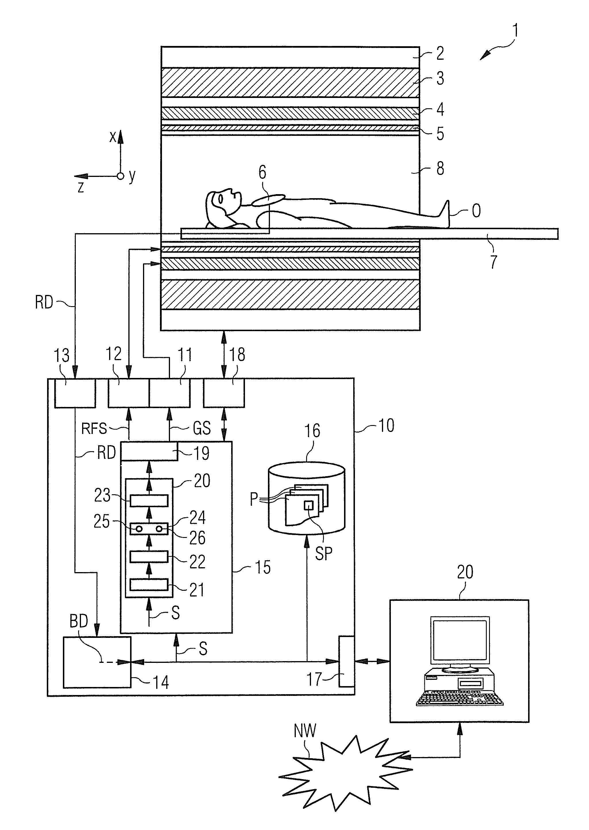
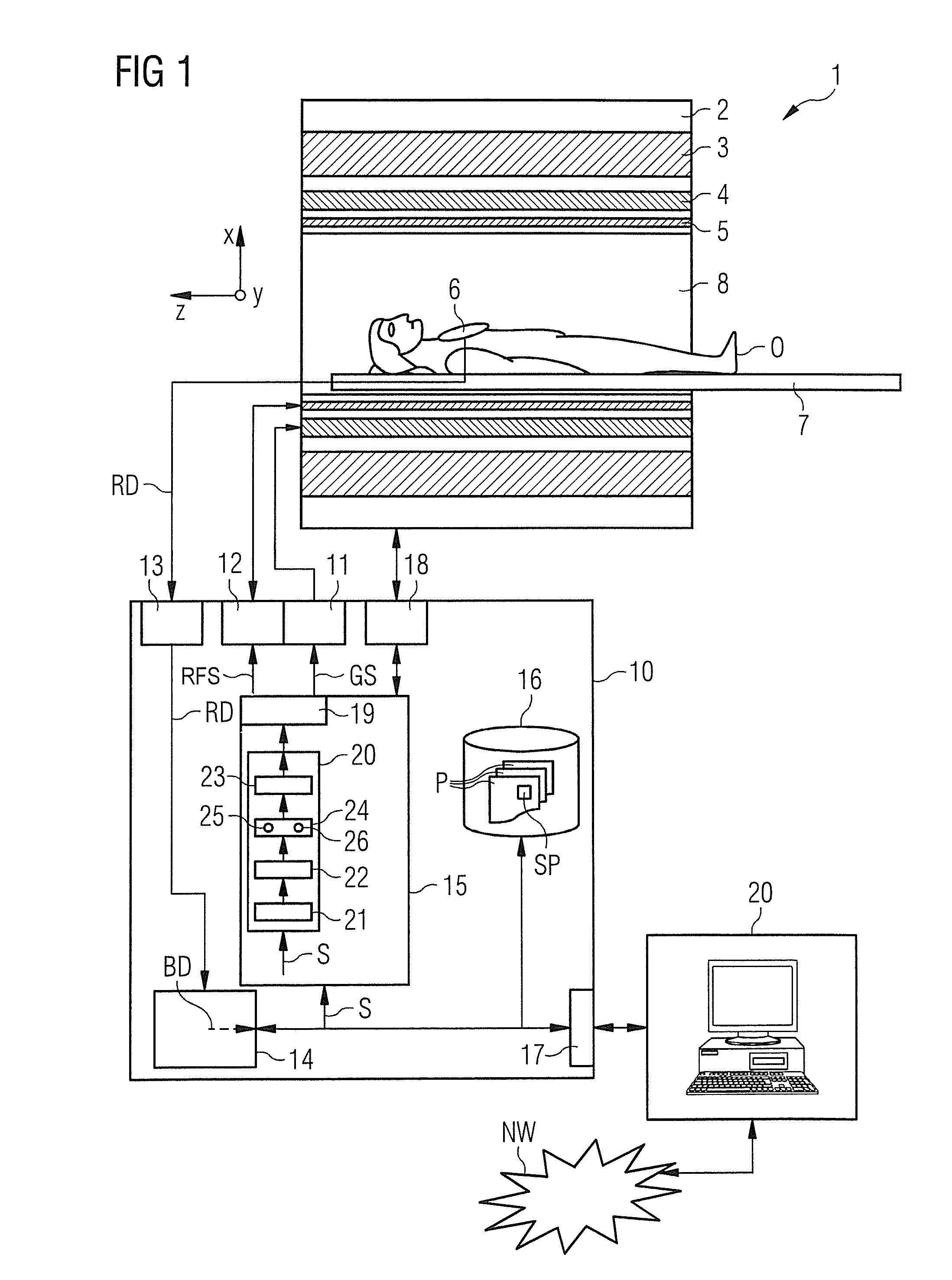
[0048]FIG. 1 shows a grossly schematic representation of an inventively designed magnetic resonance system 1. It includes the actual magnetic resonance scanner 2 surrounding a scanning bore or patient tunnel 8. A bed 7 can be slid into the patient tunnel 8 so that a patient O or examination subject thereon can be placed in a particular position within the magnetic resonance scanner 2 relative to a magnet system and radio-frequency system disposed therein during an examination or can also be moved between different positions during a scan.

[0049]Basic components...


PUM


Abstract

In an apparatus and method for pulse optimization adjustment a checking is made as to whether the optimization time resulting from a calculation time for pulse optimization of a pulse sequence section for a modifiable time interval at a predefined gradient grid density, and an associated implementation time, exceeds a real time resulting from the time interval and a buffer time. The gradient grid density for pulse optimization is reduced by a factor f if the optimization time exceeds the real time.

Description

BACKGROUND OF THE INVENTION[0001]1. Field of the Invention[0002]The invention relates to an apparatus for controlling and adjusting pulse optimization of a magnetic resonance system and to a method for controlling and adjusting pulse optimization of a magnetic resonance system.[0003]The invention further relates to a magnetic resonance system having a radio-frequency transmitting system, having a gradient system and a control device which is designed to control the radio-frequency transmitting system and the gradient system on the basis of a predefined pulse sequence in order to perform a desired scan, and having a pulse sequence optimization device.[0004]2. Description of the Prior Art[0005]In a magnetic resonance system, also known as a magnetic resonance tomography system, the body to be examined is usually exposed to a relatively high basic magnetic field, e.g. of 1, 3, 5 or 7 teslas, using a main field magnet system. In addition, a gradient system is used to apply a magnetic fi...

Claims


Application Information

Patent Timeline
Patent Type & Authority Applications(United States)
IPC IPC(8): G01R33/54G01R33/385
CPCG01R33/385G01R33/543G01R33/3854
Inventor GRODZKI, DAVIDSTOECKER, STEPHAN
Owner SIEMENS HEALTHCARE GMBH
Why Eureka
Try Eureka