Anti-reflection structure, imprint mold, method for producing Anti-reflection structure, method for producing imprint mold, and display device

a technology of anti-reflection structure and imprint mold, which is applied in the field of anti-reflection structure, imprint mold, methods for producing them, and display devices, can solve the problems of problematic reflected light affecting the view of images, and achieve the effect of sufficiently improving transmittance and reducing reflection

Inactive Publication Date: 2015-08-27
SHARP KK
View PDF13 Cites 22 Cited by
  • Summary
  • Abstract
  • Description
  • Claims
  • Application Information

AI Technical Summary

Benefits of technology

[0059]According to the present invention, while regions different in reflection characteristics are formed mixed in a structure including a moth-eye structure, reflection is sufficiently reduced and transmittance is sufficiently improved by the moth-eye structure.

Problems solved by technology

Since light reflects on the surface of the display device in bright places, the reflected light problematically hinders the view of images.

Method used


Image

  • Anti-reflection structure, imprint mold, method for producing Anti-reflection structure, method for producing imprint mold, and display device
  • Anti-reflection structure, imprint mold, method for producing Anti-reflection structure, method for producing imprint mold, and display device
  • Anti-reflection structure, imprint mold, method for producing Anti-reflection structure, method for producing imprint mold, and display device

Examples


embodiment 1

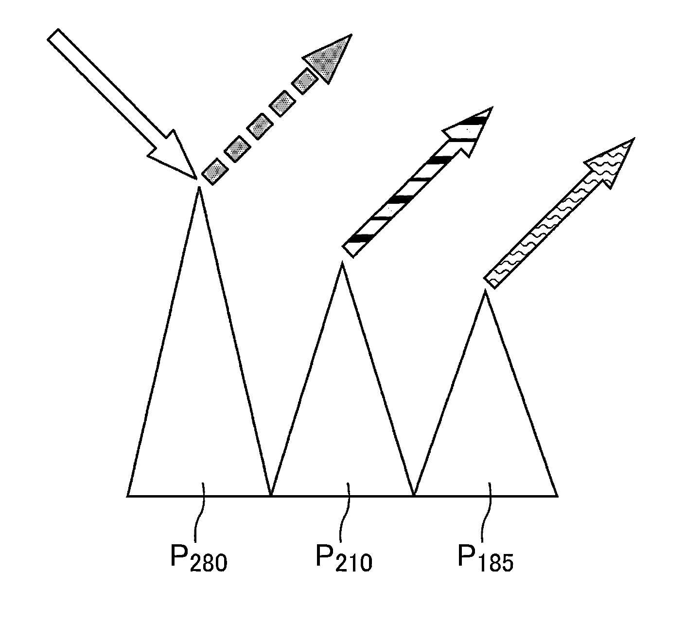
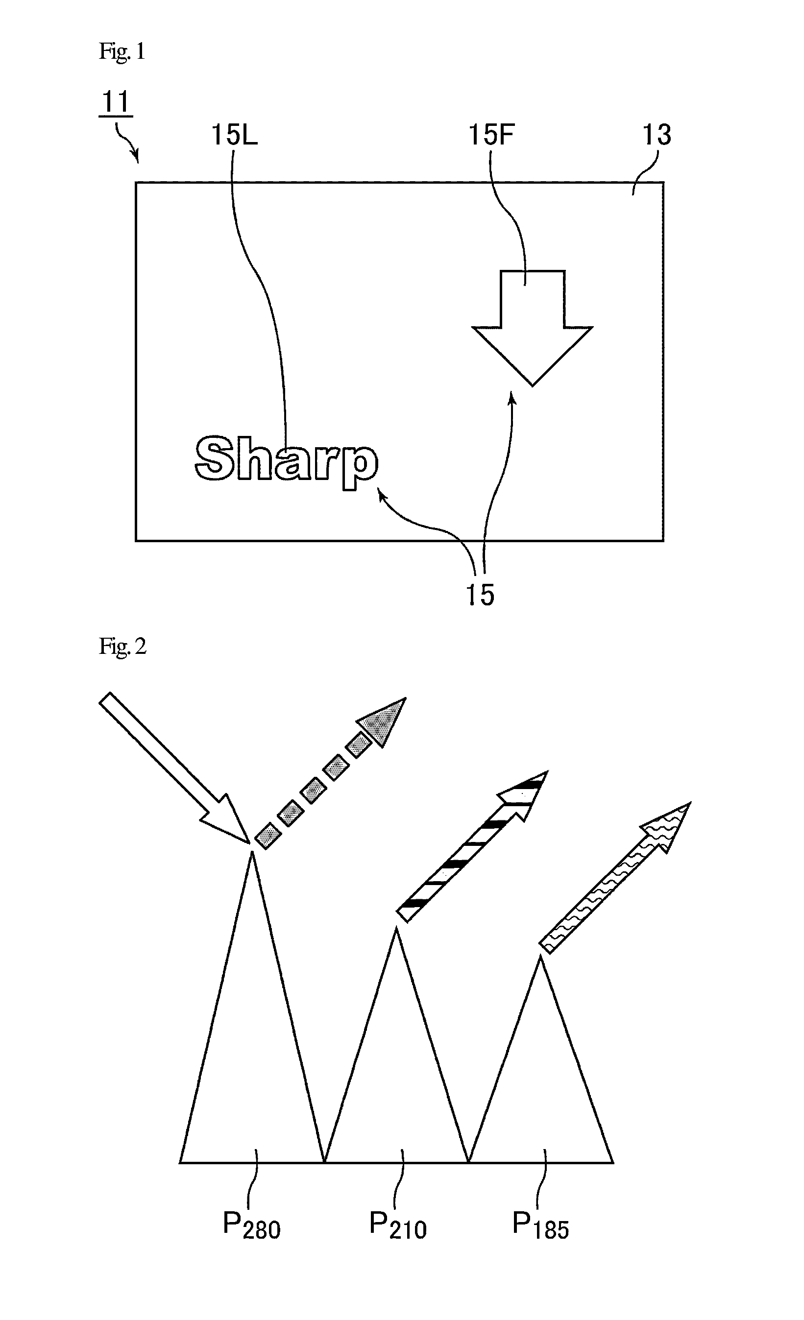
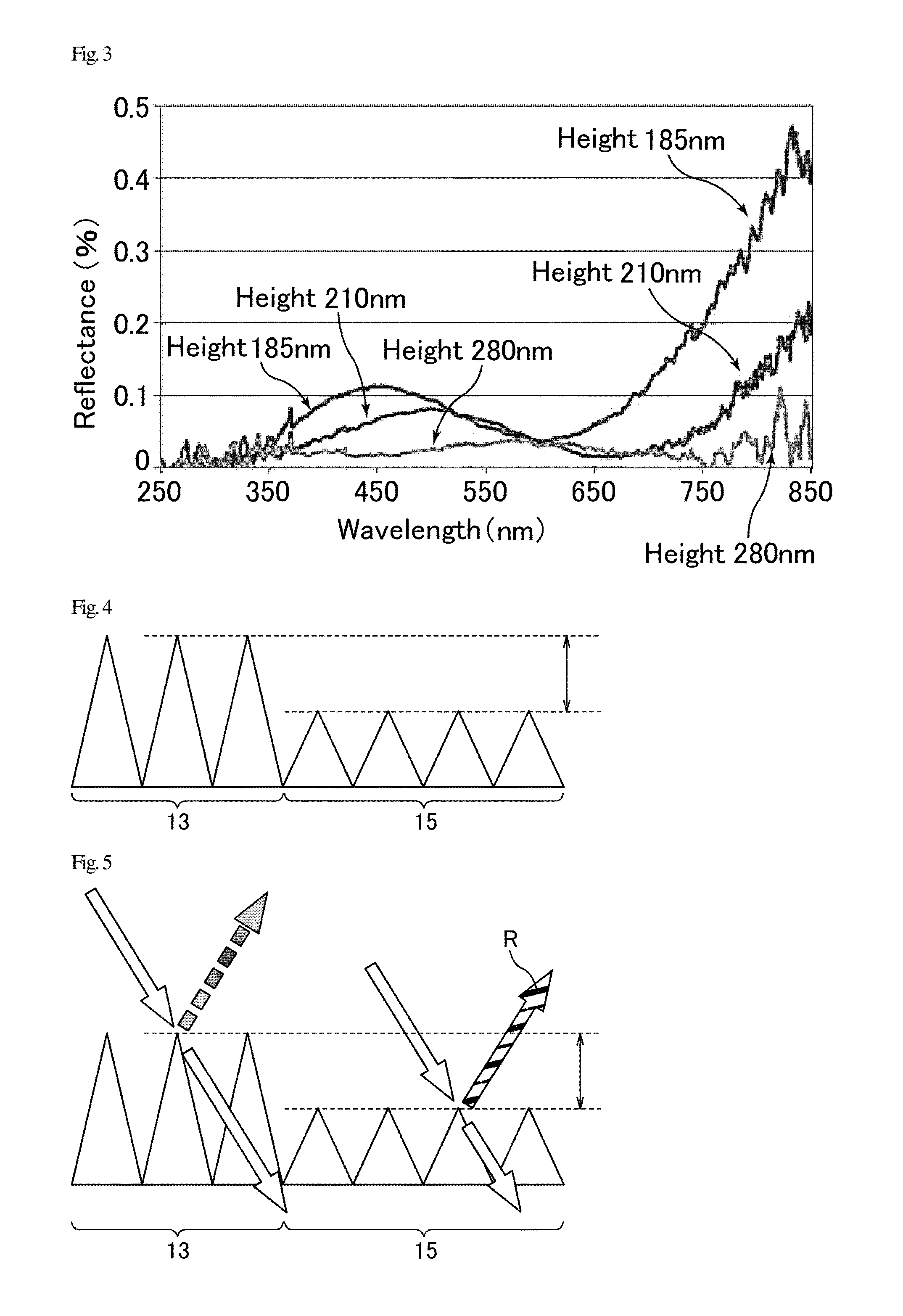
[0096]FIG. 1 is a plan view schematically illustrating an anti-reflection film of Embodiment 1. An anti-reflection film 11 of Embodiment 1 includes a first region 13 and a second region (having different characteristics from those of the first region) 15. The first region 13 includes a surface with an uneven structure (a first moth-eye structure) that is composed of a transparent resin in which protrusions are arranged at a cycle (width between the tops of any pair of the adjacent protrusions) smaller than visible light wavelengths. The second region 15 includes a surface with an uneven structure, which is different from the uneven structure in the first region, that is composed of a transparent resin in which protrusions are arranged at a cycle (width between the tops of any pair of the adjacent protrusions) smaller than visible light wavelengths. The first region 13 including a moth-eye structure and the second region 15 including a moth-eye structure are regions where the uneven ...

modified example of embodiment 1

[0121]FIG. 6 is a plan view schematically illustrating an anti-reflection film of a modified example of Embodiment 1. FIGS. 7 and 8 are each an example of a cross-sectional view schematically illustrating an anti-reflection film of a modified example of Embodiment 1, and each schematically illustrate a cross section along an A-B line illustrated in FIG. 6.

[0122]In cases where a character such as a logo, symbol, or graphic is put on the anti-reflection film (moth-eye sheet) 111 in which a moth-eye structure is formed, a method for preventing the function of the moth-eye structure in such a portion (second region 115) or a method for changing the reflection characteristics of the moth-eye structure in such a portion (second region 115) can be used.

[0123]For example, when the character “A” is put on the moth-eye sheet as illustrated in FIG. 6, the character is directly printed using an ink or the like without changing the moth-eye structure that is composed of a transparent resin, whic...

embodiment 2

[0155]FIG. 17 is a schematic view of an imprint mold of Embodiment 2. A method for preparing a moth-eye surface in which the reflection characteristics are partially changed is described in detail below.

[0156]A moth-eye structure is formed by continuous transcription of a female pattern which is formed on the surface of an imprint mold 321 with a shape such as a roll shape. An example of a method for preparing an anti-reflection film using the roll-shaped imprint mold 321 is herein described.

[0157]The roll-shaped imprint mold 321 is, for example, a roll-shaped mold made by cutting aluminum (Al) or a thin sleeve tube as a base with an aluminum film on the surface in which the aluminum surface is repeatedly anodized and etched. That is, alumina (Al2O3) with a plurality of fine holes (pores) having a size of a visible light wavelength or less formed by anodization of aluminum (hereinafter, also referred to as anodized porous alumina) is formed on a large area of the surface of the impr...


PUM

PropertyMeasurementUnit
wavelengthaaaaaaaaaa
visible light wavelengthaaaaaaaaaa
widthaaaaaaaaaa

Abstract

Disclosed are an anti-reflection structure, an imprint mold, methods for producing them and a display device capable of achieving appropriate visibility by forming regions different in reflection characteristics mixed in a film including a moth-eye structure, and sufficiently reducing reflection and sufficiently improving transmittance by the moth-eye structure. The anti-reflection structure includes a surface with an uneven structure composed of a transparent body and includes protrusions, the width between the tops of any pair of the adjacent protrusions being equal to or shorter than visible light wavelengths, the anti-reflection structure including a first region including a surface with the uneven structure, and a second region including a surface with a structure composed of a transparent body, the structure being different from the uneven structure and the second region in a plan view having a shape forming at least one selected from the group consisting of characters, symbols, and graphics.

Description

TECHNICAL FIELD[0001]The present invention relates to an anti-reflection structure, an imprint mold, methods for producing them, and a display device. The present invention specifically relates to an anti-reflection structure and an imprint mold which include a surface with a moth-eye structure, method for producing them, and a display device including a display surface with a moth-eye structure.BACKGROUND ART[0002]Flat panel display (FPD) technology has been greatly advanced, and display devices such as liquid crystal TVs and mobile devices (smartphones, tablets) including an FPD have become popular these days. FPDs are often used in bright places as is well exemplified by the application to TVs and mobile devices. Thus, good visibility of FPDs is required in not only dark places but bright places as well.[0003]An FPD is a display device generally produced using a glass substrate. Since light reflects on the surface of the display device in bright places, the reflected light proble...

Claims


Application Information

Patent Timeline
Patent Type & Authority Applications(United States)
IPC IPC(8): G02B1/11G03F7/00
CPCG03F7/0005G02B1/11G02B1/118H10K50/86G02F1/133502
Inventor FUJII, AKIYOSHITAGUCHI, TOKIO
Owner SHARP KK
Why Eureka
Try Eureka