
Image processing apparatus and method for controlling image processing apparatus

a technology of image processing apparatus and image sensor, which is applied in the direction of color signal processing circuit, color television details, television system, etc., can solve the problems of defective pixel, defective pixel, erroneous correction, etc., and achieve the effect of correcting the defective pixel

Active Publication Date: 2015-08-27
CANON KK
View PDF1 Cites 7 Cited by
  • Summary
  • Abstract
  • Description
  • Claims
  • Application Information

AI Technical Summary

Benefits of technology

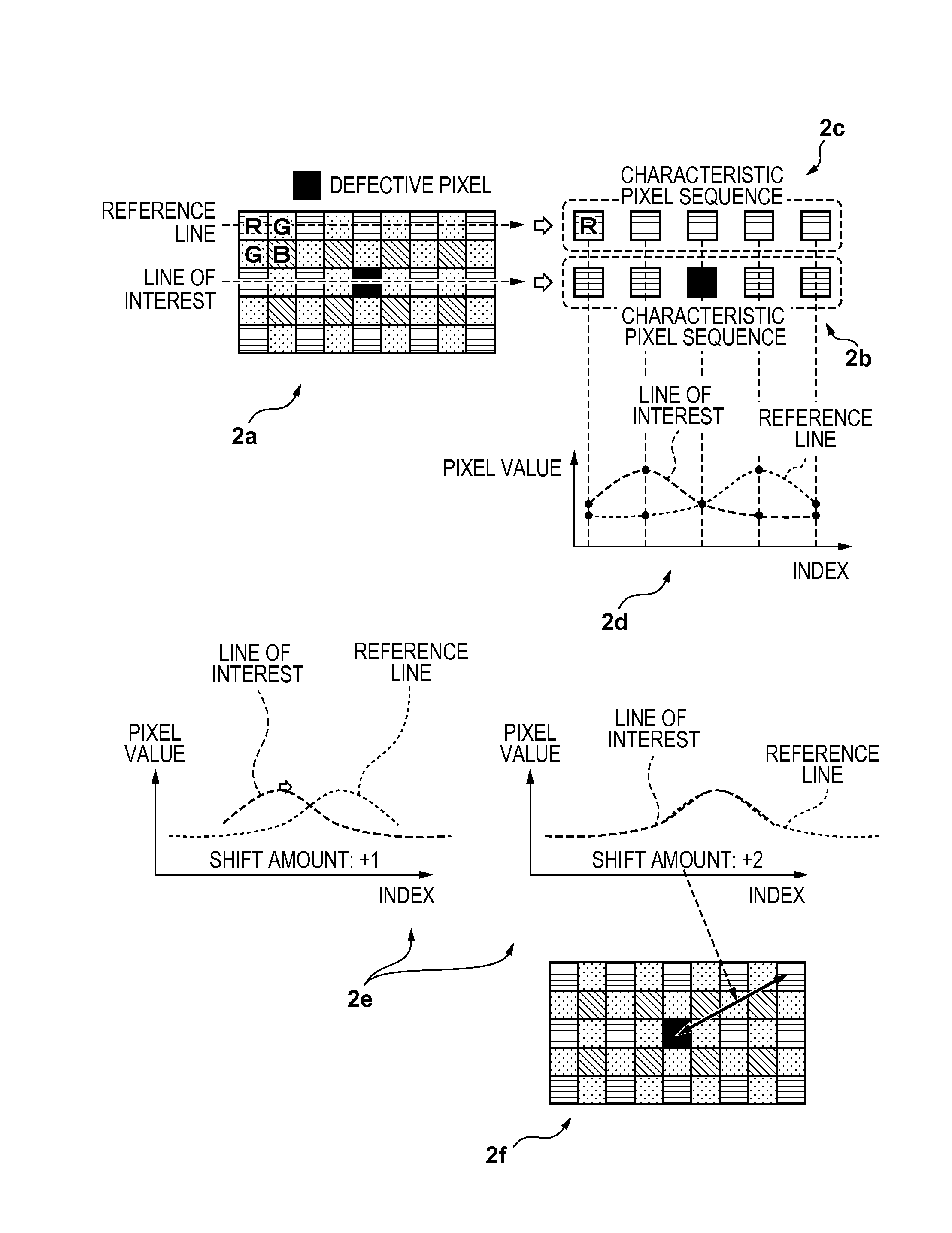
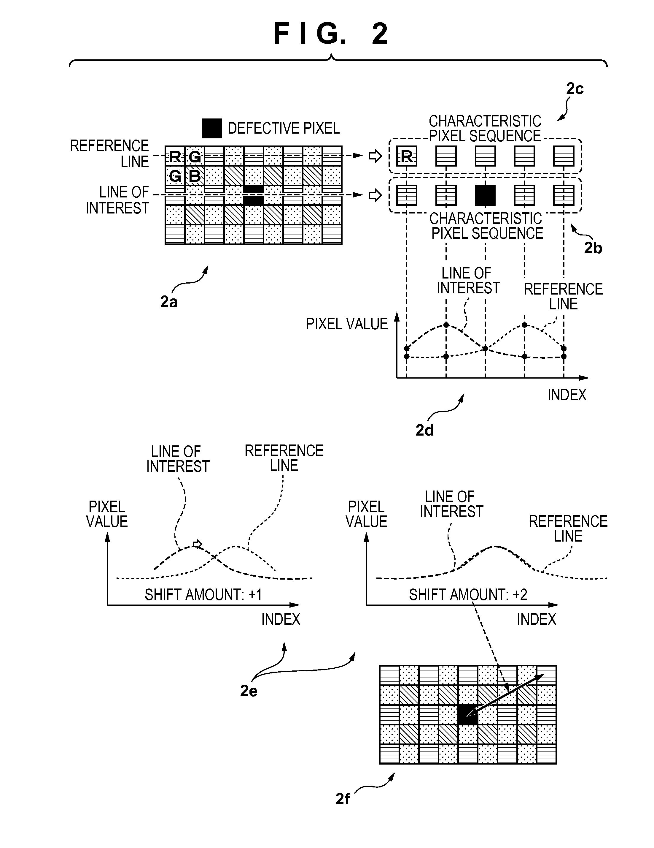
The present invention provides an image processing apparatus and method that can accurately correct defective pixels even when the surrounding pixels don't have a specific angle. The apparatus sets a correction target pixel and its surrounding areas in the image, computing the correlation between the pixels in each area. A correction value is then computed to correct the value of the correction target pixel based on the amounts of correlation in its surrounding areas. The method also assigns a larger weight to the correlation in the portion closest to the correction target pixel. This results in a more accurate and efficient correction of defective pixels.

Problems solved by technology

In general, a defective pixel exists in the image sensor since a large number of pixels are provided therein.
However, with the conventional techniques disclosed in the aforementioned patent documents, a defective pixel can be accurately corrected for a subject having a predetermined specific angle, but there are cases where erroneous correction occurs in the case of a subject having a different angle.
However, if, for example, pixel values of a subject having a repetitive pattern shown in FIG. 16C are as shown in FIG. 16D due to the defective pixel, there are cases where the angle of the subject cannot be correctly detected based on a difference between two points.

Method used


Image

  • Image processing apparatus and method for controlling image processing apparatus
  • Image processing apparatus and method for controlling image processing apparatus
  • Image processing apparatus and method for controlling image processing apparatus

Examples


first embodiment

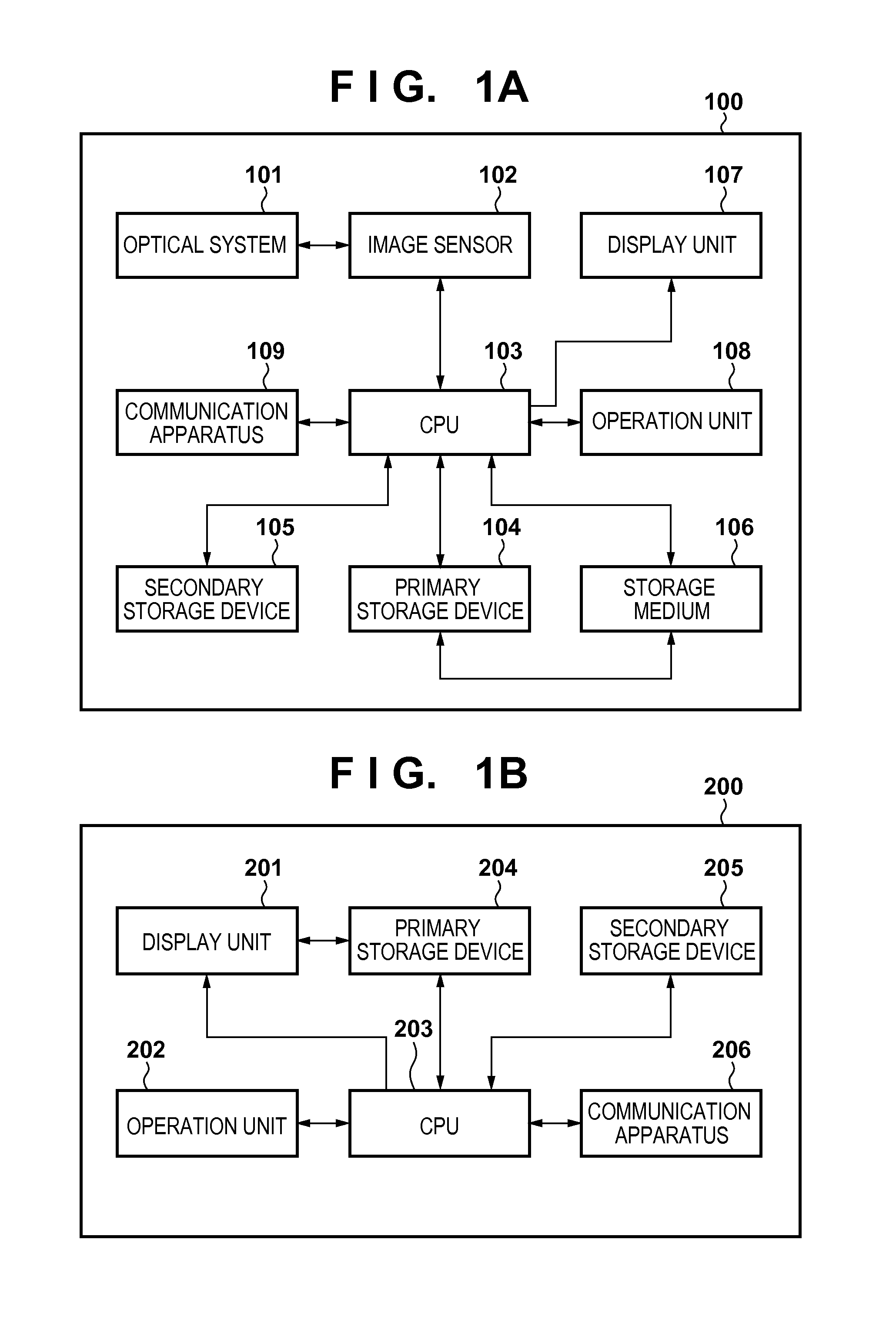
[0030]FIG. 1A is a block diagram showing an exemplary functional configuration of an image capture apparatus (or image processing apparatus) 100, which is an exemplary image processing apparatus according to an embodiment of the present invention.

[0031]The image capture apparatus 100 is an apparatus such as a digital camera or a digital video camera that photographs a subject and obtains data (image data) representing an image of the subject. An optical system 101 has a lens, a shutter, and a diaphragm, and forms an optical image of the subject on an image sensor 102, under the control of a CPU 103. The image sensor 102, which may be a CCD or a CMOS image sensor, performs photoelectric conversion on the formed optical image of the subject at each pixel, and converts it into an analog image signal. The CPU 103 converts the analog image signal into a digital image signal (image data), and applies thereto so-called developing processing, such as white balancing adjustment and color int...

second embodiment

[0065]The first embodiment has described the correction method in the case where the defective pixel is a pixel of a color that appears once in each repetition unit of the color filter, such as an R pixel or a B pixel in a Bayer array. The present embodiment relates to a correction method in the case where the defective pixel is a pixel that appears in each pixel line, such as a G pixel in a Bayer array.

[0066]In the case where an R pixel or a B pixel in a Bayer array is a defective pixel, since the repetition unit is constituted by two pixels, a pixel of the same color as the defective pixel does not exist in an adjoining pixel line and is located at a position separated from the defective pixel by at least two pixels, and therefore the reference line is set on a pixel line separated from the line of interest by two pixels. However, for example, if a G pixel is a defective pixel as shown in part 6a of FIG. 6, a pixel of the same color as the defective pixel exists on an adjoining pi...

third embodiment

[0070]The first and second embodiments have described the correction method in the case where the defective pixel is isolated. The present embodiment will describe a correction method in the case where defective pixels of the same color successively exist. Such defective pixels occur due to manufacturing tolerance or aged deterioration, as well as in the case where pixels for focus detection are arranged in the image sensor as shown in part 7a of FIG. 7. Since the focus detection pixels generate a signal for performing focus detection in a phase difference detection method, their range of light reception is narrower than usual pixels, or the color filter is not provided therein, and consequently an obtained pixel value is different from that of usual pixels. Accordingly, correction needs to be performed by considering these focus detection pixels to be successive defective pixels of the same color, as shown in part 7b of FIG. 7.

[0071]Assuming that the line of interest is in the hori...


PUM


Abstract

A first area of an image is generated from pixels existing on a line of interest that is set so as to pass through a pixel corresponding to a correction target pixel. Second areas are generated, each second area based on the positions of pixels existing on at least one reference lines that are set so as not to pass through the correction target pixel. The value of the pixel corresponding to the correction target pixel is corrected using a value of a pixel on each of the at least one reference lines, the value being determined based on the amounts of correlation between the respective second areas and the first area. The amounts of correlation are computed while applying a larger weight to a correlation in a portion that is closer to the pixel corresponding to the correction target pixel.

Description

BACKGROUND OF THE INVENTION[0001]1. Field of the Invention[0002]The present invention relates to an image processing apparatus and a method for controlling the image processing apparatus, and relates in particular to a technique for correcting a defective pixel.[0003]2. Description of the Related Art[0004]An image capture apparatus such as a digital camera takes an image using an image sensor such as a CMOS sensor. In general, a defective pixel exists in the image sensor since a large number of pixels are provided therein. As a technique for correcting the value of such a defective pixel, a method is known that uses a pixel value estimated from one or more values of one or more non-defective pixels existing at the periphery of the defective pixel, as the pixel value at a defective pixel position. Hereinafter, in the present specification, obtaining a pixel value at the defective pixel position that would have been obtained if the pixel were not defective will be referred to as defec...

Claims


Application Information

Patent Timeline
Patent Type & Authority Applications(United States)
IPC IPC(8): H04N5/367
CPCH04N5/367H04N25/683H04N25/704
Inventor FURUYA, KOHEI
Owner CANON KK
Learn More