
Method and apparatus of selecting transmission rate in wireless transmission system

a transmission rate and wireless transmission technology, applied in the direction of wireless communication, channel coding adaptation, wireless commuication services, etc., can solve the problems of reducing signal level, avoiding frame errors, and not being able to solve the scenario illustrated in fig. 1 if not a common cas

Inactive Publication Date: 2015-08-27
ELECTRONICS & TELECOMM RES INST
View PDF9 Cites 2 Cited by
  • Summary
  • Abstract
  • Description
  • Claims
  • Application Information

AI Technical Summary

Benefits of technology

The present invention provides a method and apparatus for selecting the optimal transmission rate in a wireless transmission system based on network conditions and input criteria. This can be done without receiving any feedback from the destination node and can be easily applied to different networks without changing hardware. The QoS-aware wireless network takes into consideration the requirements per service class based on multiple criteria, thus allowing for the selection of the optimal transmission rate in a simple and efficient manner.

Problems solved by technology

As the MCS index increases, a frame error is more likely to occur.
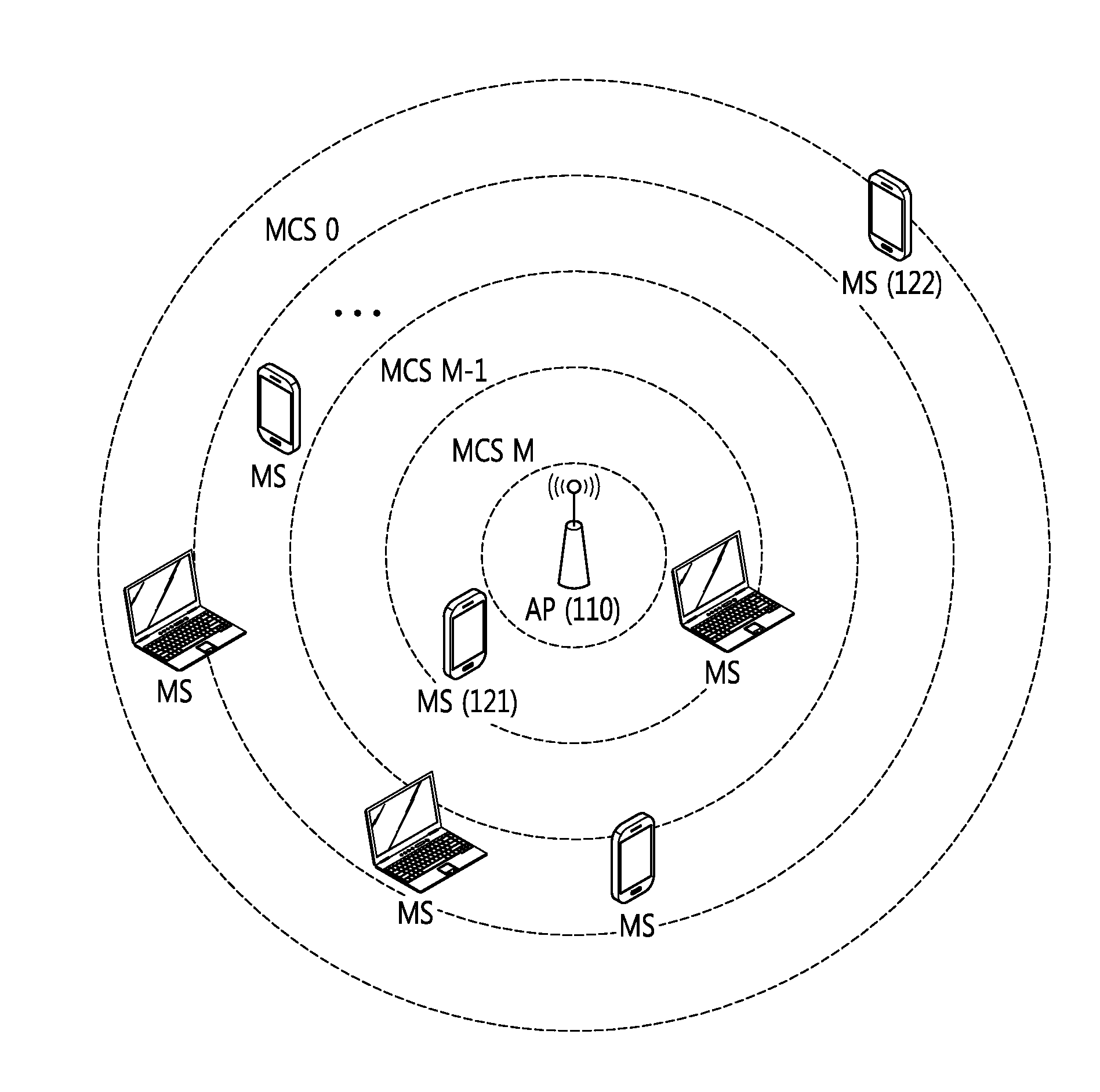
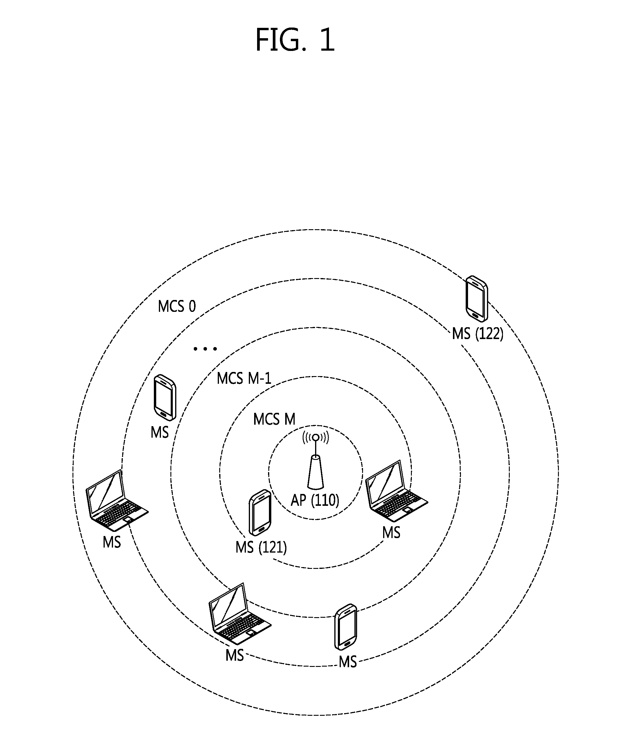
However, since a signal may propagate through a wall or human body, the scenario illustrated in FIG. 1 is not a common case.
In some cases, the signal level may be significantly decreased due to an obstacle such as wall even when the transmitter is located close to the receiver.
Accordingly, the awareness of the physical distance between the MS and the AP is not a solution to selection the optimal transmission rate in an actual scenario.
However, instability of wireless channel may cause frequent updating, thus inducing high overload.
Accordingly, sending feedback information is not a solution either.
In such scenario, the traditional maximum throughput-based approach is not always the best solution.
However, such scheme merely selects an MCS index according to a resource assigning scheme and does not choose a transmission rate considering requirements per service class.

Method used


Image

  • Method and apparatus of selecting transmission rate in wireless transmission system
  • Method and apparatus of selecting transmission rate in wireless transmission system
  • Method and apparatus of selecting transmission rate in wireless transmission system

Examples


Embodiment Construction

[0033]Hereinafter, embodiments of the present invention are described below in detail with reference to the accompanying drawings so that the embodiments can be easily practiced by one of ordinary skill in the art. However, various changes may be made without being limited thereto. What is irrelevant to the present invention was skipped from the description for clarity, and like reference denotations are used to refer to like or similar elements throughout the specification.

[0034]As used herein, when an element “includes” another element, the element may further have the other element unless stated otherwise. As used herein, the term “unit” denotes a unit of performing at least one function or operation and may be implemented in hardware, software, or a combination thereof.

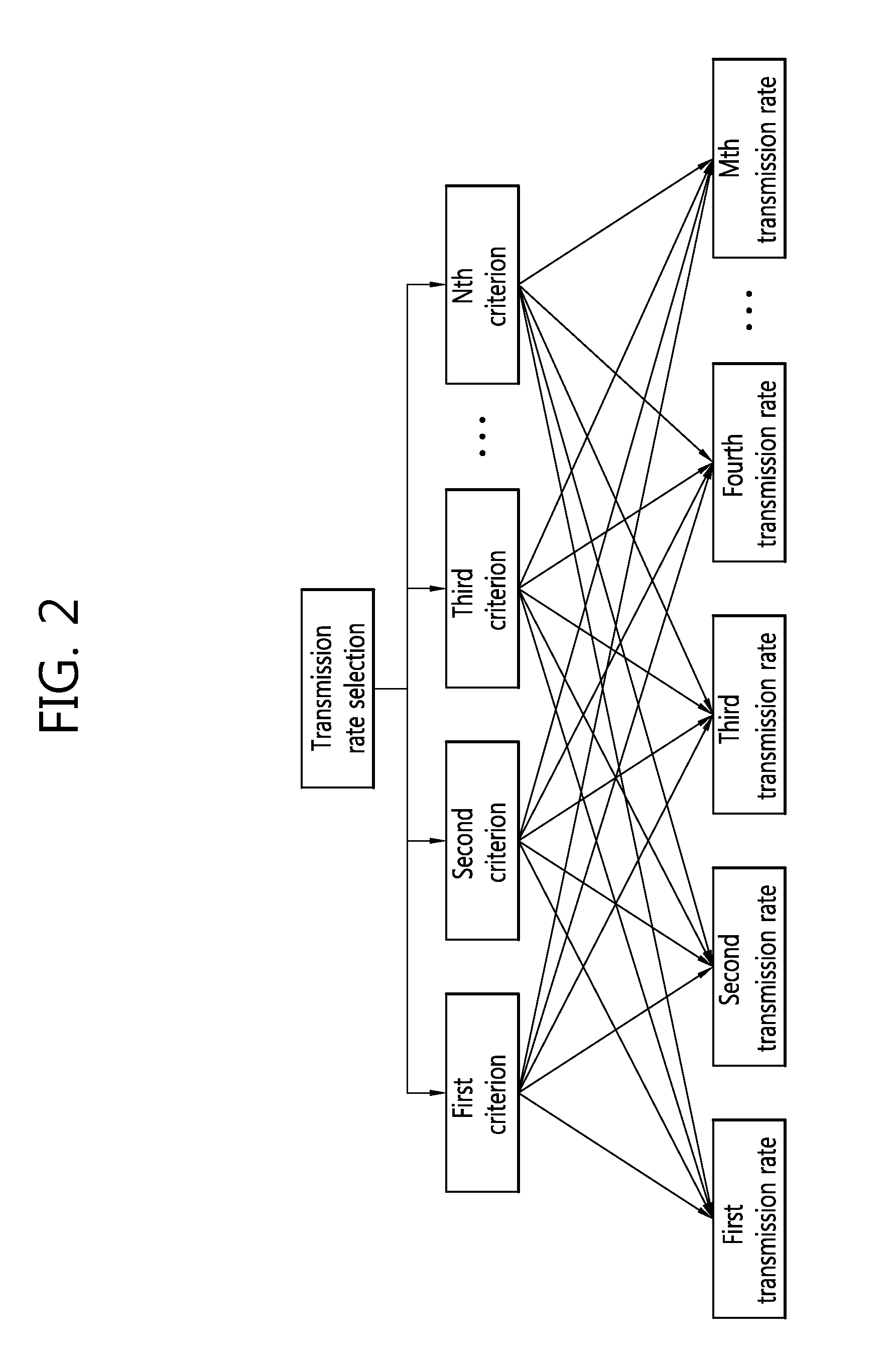
[0035]FIG. 2 is a view illustrating a process of hierarchically selecting a transmission rate based on a plurality of criteria.

[0036]A typical QoS (Quality of Service) aware wireless network has a plurality of tra...


PUM


Abstract

A method and apparatus of selecting a transmission rate in a wireless transmission system are provided. The method of selecting a transmission rate by a transmission rate selecting apparatus may comprise assigning a weight to each of criteria for selecting a transmission rate per service class, calculating a score for each transmission rate per service class using statistics information collected for a plurality of transmission rates based on the weight-assigned criteria, and selecting a transmission rate for a service class based on the calculated score.

Description

CROSS-REFERENCE TO RELATED APPLICATION[0001]Priority to Korean patent application number 2014-0021537 filed on Feb. 24, 2014, the entire disclosure of which is incorporated by reference herein, is claimed.BACKGROUND OF THE INVENTION[0002]1. Technical Field[0003]Embodiments of the present invention concern a method and apparatus of selecting the optimal transmission rate per service class to achieve the best performance in QoS (Quality of Service) aware wireless networks.[0004]2. Discussion of Related Art[0005]Wireless networks have become one of the major schemes to access end user data due to low costs and high-speed connectivity. As more and more devices are equipped with a wireless network interface, demand for wireless networks is quickly increasing. Accordingly, development of applications, as well as smart devices, becomes more critical to satisfy end users' demand. Each application has its own requirements in view of QoS (Quality of Service) parameters, such as, e.g., through...

Claims


Application Information

Patent Timeline
Patent Type & Authority Applications(United States)
IPC IPC(8): H04W72/06H04W24/10H04L1/00H04W72/08H04W72/54
CPCH04W72/06H04L1/0003H04W24/10H04W72/087H04W28/22H04L1/0009H04L1/0034H04L1/0015
Inventor KIM, IGORKO, GWANG ZEENOH, JIN HYUNGKANG, HYUN DUKSONG, MYUNG SUN
Owner ELECTRONICS & TELECOMM RES INST
Learn More