Control device for vehicle drive device

a technology of control device and vehicle drive, which is applied in the direction of propulsion using engine-driven generators, transportation and packaging, propulsion parts, etc., can solve the problems of inability to use the path with better transmission efficiency, inability to meet the needs of vehicles, etc., to improve the fuel efficiency of the vehicle, improve the fuel efficiency, and improve the effect of transmission ra

Active Publication Date: 2014-05-08
TOYOTA JIDOSHA KK
View PDF0 Cites 10 Cited by
  • Summary
  • Abstract
  • Description
  • Claims
  • Application Information

AI Technical Summary

Benefits of technology

[0007]Consequently, since the control device of a vehicle drive device has an electric path through which power is electrically transmitted by giving / receiving electric power between the first electric motor and the second electric motor and a mechanical path through which power is mechanically transmitted via the hydraulic power transmission device, and the control device of a vehicle drive device can control an operating point of the engine without being constrained by a rotation speed of the output-side rotating element by adjusting a torque of the first electric motor, for example, the engine can be driven at the optimal operating point for the fuel efficiency improvement and the fuel efficiency improvement of the vehicle can be achieved. Additionally, since the vehicle drive device further includes the capacity variable device varying the capacity of the hydraulic power transmission device, a change can be made to the torque generated in the input-side rotating element uniquely determined based on the capacity of the hydraulic power transmission device at the operating point of the engine arbitrarily controlled by adjusting the first electric motor torque. Therefore, at the operating point of the engine in this case, a proportion between the torque transmitted to the mechanical path side and the torque transmitted to the electric path side can be changed to increase a proportion of the power transmission through the path with a better transmission rate out of the mechanical path and the electric path. Therefore, when the engine operating point is controlled by adjusting the first electric motor torque, further fuel efficiency improvement of the vehicle can be achieved.
[0008]The second aspect of the invention provides the control device of a vehicle drive device recited in the first aspect of the invention, wherein when the operating point of the engine is controlled to the same target operating point, if power transmission efficiency is improved at the time of transmission of power from the engine through the electric path and the mechanical path, the capacity variable device changes the capacity of the hydraulic power transmission device. Consequently, when the engine operating point is controlled by adjusting the torque of the electric motor, further fuel efficiency improvement of the vehicle can properly be achieved.
[0009]The third aspect of the invention provides the control device of a vehicle drive device recited in the first or second aspect of the invention, wherein if a requested load is equal to or less than a predetermined value set in advance such that the requested load is supportable by power transmission through the electric path in a range in which the requested load is equal to or less than the predetermined value, the capacity variable device is allowed to make a change toward a smaller capacity of the hydraulic power transmission device. Consequently, if the requested load is greater than the predetermined value, this avoids the possibility of reducing the torque generated in the input-side rotating element and increasing the first electric motor torque due to the change toward smaller capacity of the hydraulic power transmission device and thus causing the state in which the increased torque cannot be output by the rated output of the first electric motor.
[0010]The fourth aspect of the invention provides the control device of a vehicle drive device recited in any one of the first to third aspects of the invention, wherein if the transmission efficiency through the electric path is better than a transmission efficiency through the mechanical path, the capacity variable device decreases the capacity of the hydraulic power transmission device. Consequently, the torque generated in the input-side rotating element can be reduced to increase the first electric motor torque, thereby increasing the proportion of power transmission through the electric path with the better transmission efficiency. Therefore, when the engine operating point is controlled by adjusting the first electric motor torque, further fuel efficiency improvement of the vehicle can be achieved.
[0011]The fifth aspect of the invention provides the control device of a vehicle drive device recited in any one of the first to fourth aspects of the invention, wherein if the transmission efficiency through the mechanical path is better than a transmission efficiency through the electric path, the capacity variable device increases the capacity of the hydraulic power transmission device. Consequently, the torque generated in the input-side rotating element can be increased to reduce the first electric motor torque, thereby increasing the proportion of power transmission through the mechanical path with the better transmission efficiency. Therefore, when the engine operating point is controlled by adjusting the first electric motor torque, further fuel efficiency improvement of the vehicle can be achieved.
[0012]The sixth aspect of the invention provides the control device of a vehicle drive device recited in any one of the first to fifth aspects of the invention, wherein the torque of the first electric motor is adjusted such that a sum of an engine torque and the torque of the first electric motor is balanced with an input-side load torque generated in the input-side rotating element depending on a speed ratio of the hydraulic power transmission device. Consequently, the first electric motor torque can easily be adjusted based on the hydraulic characteristics of the hydraulic power transmission device.

Problems solved by technology

As a result, at the engine operating point during this control, a path with better transmission efficiency may not sufficiently be used.
For example, although power transmission efficiency during transmission of power from the engine may be improved by increasing a proportion of power transmission through the path with better transmission efficiency, this may not be possible.

Method used


Image

  • Control device for vehicle drive device
  • Control device for vehicle drive device
  • Control device for vehicle drive device

Examples


example

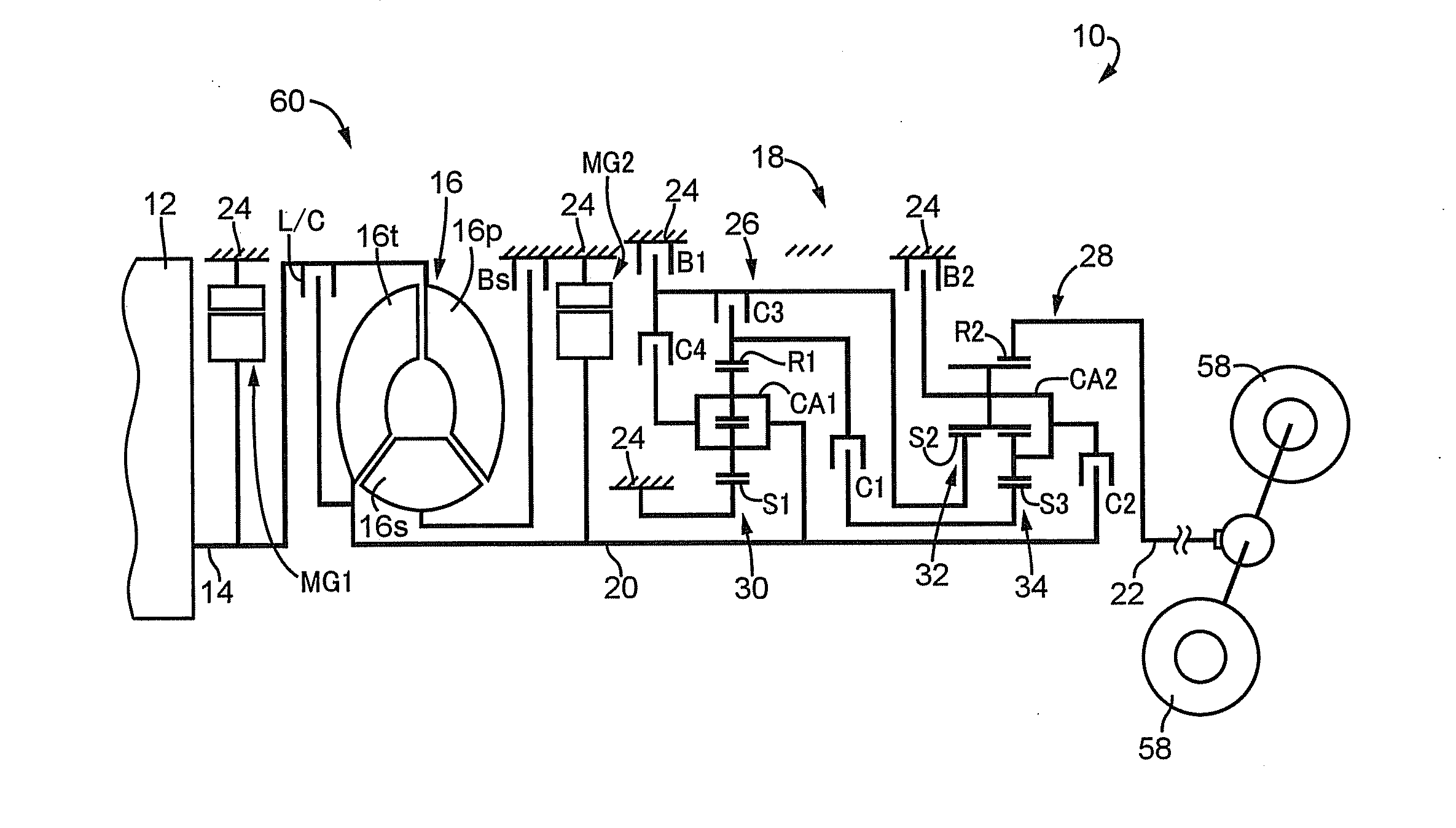
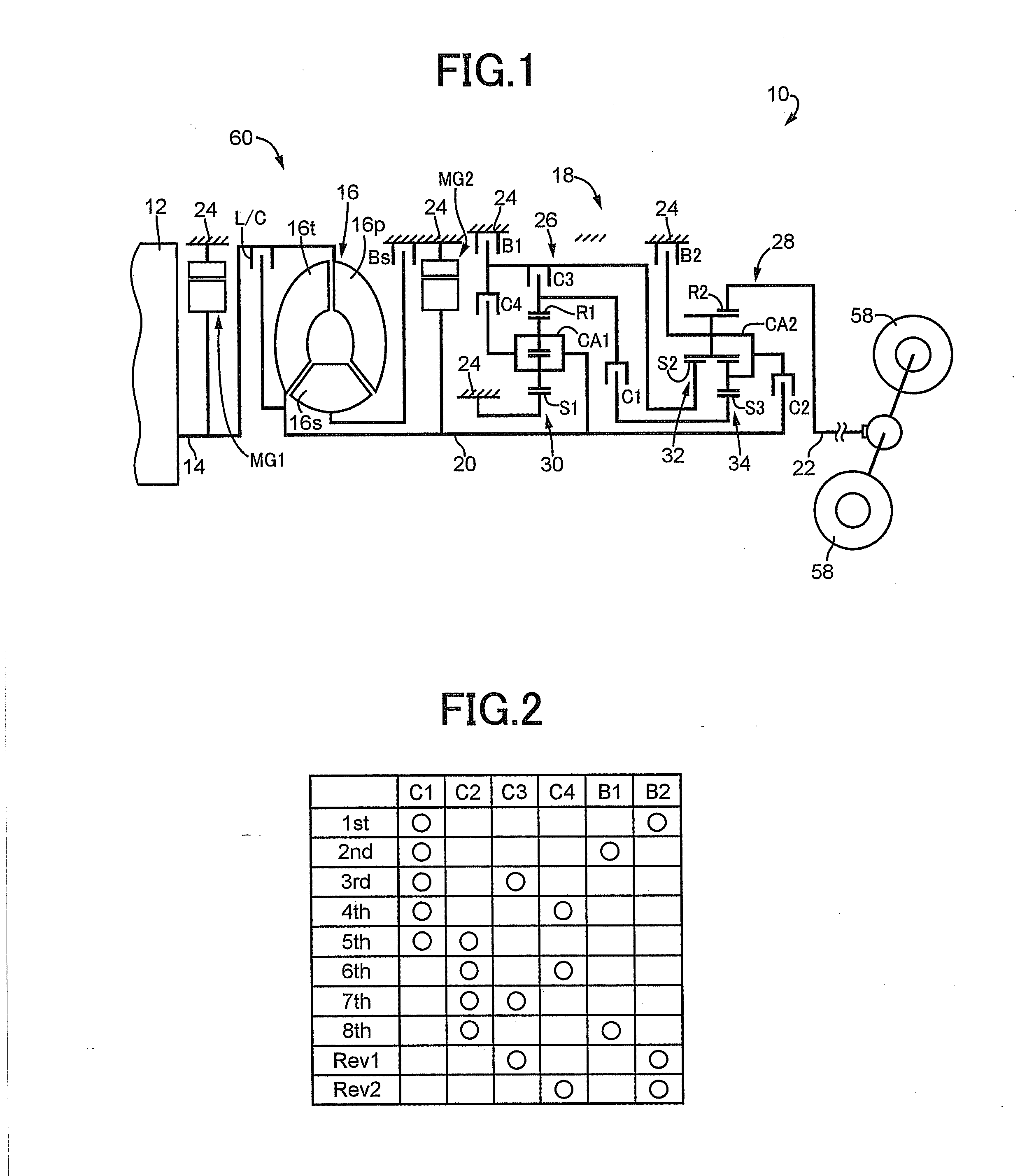
[0045]FIG. 1 is a schematic for explaining a configuration of a vehicle drive device 10 of an example of the present invention. In FIG. 1, the vehicle drive device 10 is preferably employed in FR (front-engine rear-drive) type vehicles and includes an engine 12 made up of an internal-combustion engine, a torque converter (hydraulic power transmission device) 16 coupled to a crankshaft 14 of the engine 12, an automatic transmission 18 disposed between the torque converter 16 and drive wheels 58 and coupled to the output side of the torque converter 16, a first electric motor MG1 disposed between the engine 12 and the torque converter 16 and coupled to the crankshaft 14, and a second electric motor MG2 disposed between the torque converter 16 and the automatic transmission 18 and coupled to an input shaft 20 of the automatic transmission 18. The torque converter 16, the automatic transmission 18, the first electric motor MG1, the second electric motor MG2, etc., are configured symmetr...


PUM


Abstract

A control device of a vehicle drive device comprises a hydraulic power transmission device having an input-side rotating element to which power from an engine is input and an output-side rotating element outputting power to drive wheels, a first electric motor directly or indirectly coupled to the input-side rotating element, and a second electric motor directly or indirectly coupled to the drive wheels, the vehicle drive device further comprising an electric path through which power is electrically transmitted by giving/receiving electric power between the first electric motor and the second electric motor and a mechanical path through which power is mechanically transmitted via the hydraulic power transmission device, the control device of the vehicle drive device being configured to control an operating point of the engine by adjusting a torque of the first electric motor, the control device being configured to adjust the torque of the first electric motor such that a sum of an engine torque and the torque of the first electric motor is balanced with an input-side load torque generated in the input-side rotating element depending on a speed ratio of the hydraulic power transmission device when the operating point of the engine is controlled, the control device being configured to calculate the input-side load torque based on engine rotation speed indicated by the target engine operating point and determine the torque of the first electric motor based on the engine torque indicated by the target engine operating point and the input-side load torque, the vehicle drive device further comprising a capacity variable device varying a characteristic of a capacity coefficient of the hydraulic power transmission device relative to a speed ratio of the hydraulic power transmission device that is a hydraulic characteristic of the hydraulic power transmission device for determining the input-side load torque.

Description

TECHNICAL FIELD[0001]The present invention relates to a control device of a vehicle drive device including an engine, an electric motor, and a hydraulic power transmission device such that power of the engine can be transmitted through a plurality of transmission paths.BACKGROUND ART[0002]A vehicle drive device is well known that includes a hydraulic power transmission device having an input-side rotating element to which power from an engine is input and an output-side rotating element outputting .power to drive wheels. For example, this corresponds to a vehicle drive device described in Patent Document 1. Such a vehicle drive device has an engine rotation speed (corresponding to a rotation speed of the input-side rotating element of the hydraulic power transmission device) passively determined depending on a vehicle speed (corresponding to a rotation speed of the output-side rotating element of the hydraulic power transmission device), a hydraulic characteristic of the hydraulic p...

Claims


Application Information

Patent Timeline
Patent Type & Authority Applications(United States)
IPC IPC(8): B60W20/00B60L50/16
CPCY10S903/902B60W20/10B60K6/445B60K6/547B60W10/026B60W10/06B60W10/08B60W10/10Y02T10/62B60W10/023B60W30/1882
Inventor TABATA, ATSUSHIIMAMURA, TATSUYA
Owner TOYOTA JIDOSHA KK
Why Eureka
Try Eureka