Industrial robot

a robot and industrial technology, applied in the field of industrial robots, can solve the problems of line breakage, resistance to arm and/or wrist pivoting, and risk of damage, and achieve the effect of not increasing the slack of a cable, facilitating the installation of a cable, and reducing the outside appearan

Active Publication Date: 2015-09-03
NACHI-FUJIKOSHI
View PDF18 Cites 31 Cited by
  • Summary
  • Abstract
  • Description
  • Claims
  • Application Information

AI Technical Summary

Benefits of technology

[0007]In view of the above described deficiencies, it is an object of the present invention to provide a robot which does not increase a slack of a cable and degrade the outside appearance, but facilitates the work of installing a cable and prevents uncontrollable movement of the cable during operation of the robot.

Problems solved by technology

If the cable is excessively pulled when the arm and / or the wrist are pivoted, there is a risk of causing damage such as line breakage.
However, if the slack is too long, it may cause resistance against pivoting of the arm and / or the wrist, or may interfere with peripheral members.
Moreover, a phenomenon that the cable “moves uncontrollably” may occur when the arm and / or wrist move at a high speed.
Further, the outside appearance of the robot becomes degraded.

Method used


Image

  • Industrial robot
  • Industrial robot
  • Industrial robot

Examples


embodiment 1

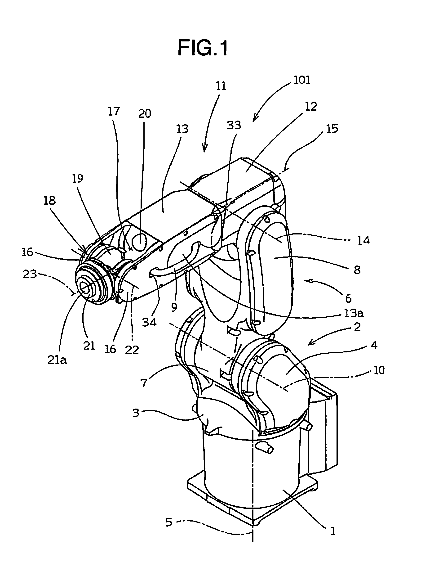
[0032]First, a general configuration of a robot 101 according to a first embodiment will be described. As shown in FIG. 1, a frame 2 is placed on a base 1 which is installed on an installation surface such as a floor surface. This frame 2 includes a base plate part 3 disposed on an upper surface of the base 1, and a pair of stand plate parts 4 which stand obliquely upward from peripheral edges of the base plate part 3, respectively. Moreover, a motor (not shown) for pivotally moving the entire frame 2 in a horizontal plane (in a plane parallel with the floor surface) is attached to the upper surface of the base plate part 3. By rotating the motor shaft of the motor in a predetermined direction, the frame 2 pivots about a first pivot axis 5 provided perpendicular to the installation surface.

[0033]A lower half part of a lower arm 6 is attached between the pair of stand plate parts 4 of the frame 2. The lower half part of the lower arm 6 has a substantially cylindrical shape and consti...

embodiment 2

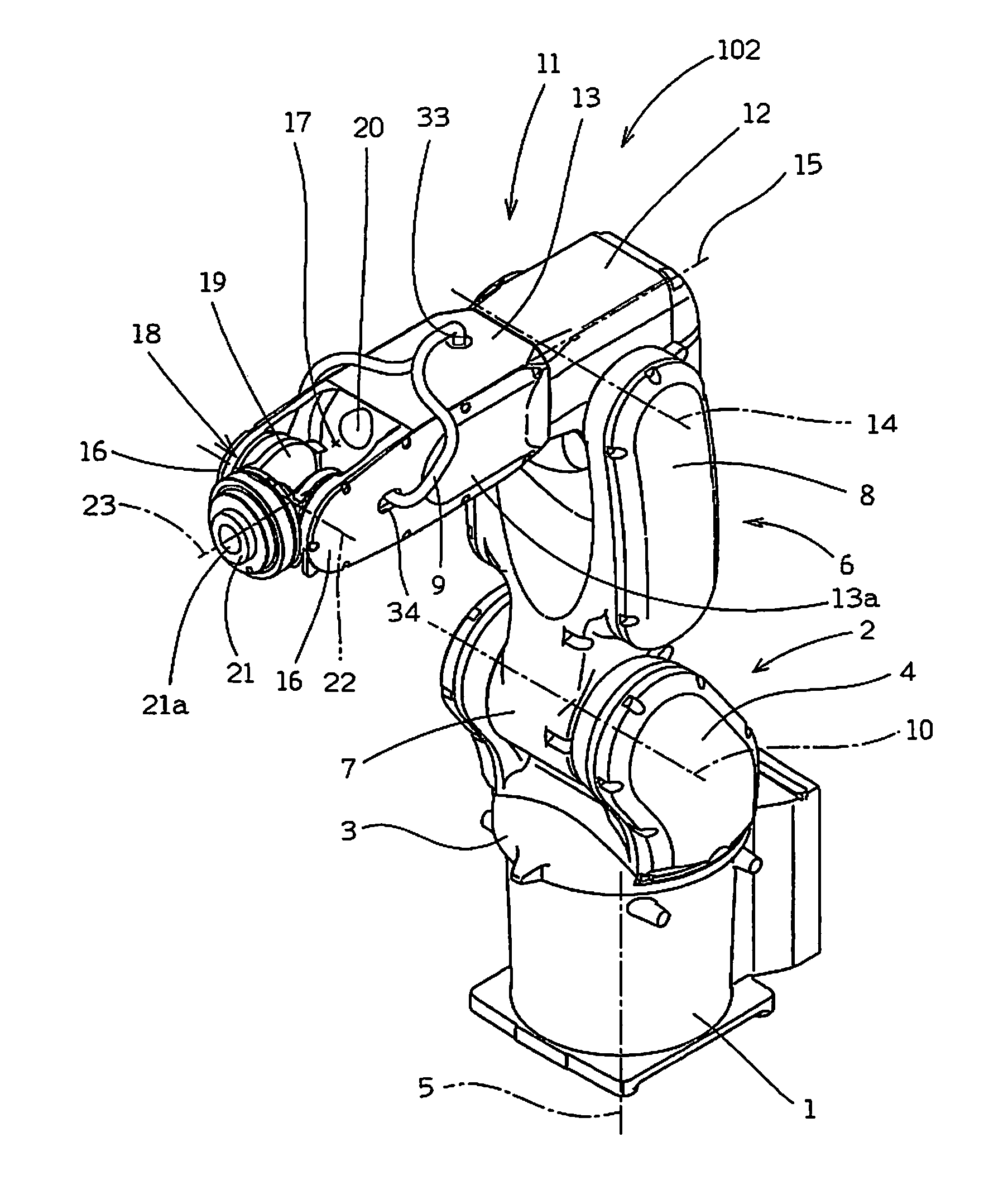
[0049]In the case of the robot 101 according to the first embodiment, the single first hole 33 and the single second hole 34 are provided only in the sidewall part 13a on one side of the second upper arm part 13. In contrast to this, in a robot 102 according to a second embodiment shown in FIG. 5, one first hole 33 is provided in an upper wall part 13b of the second upper arm part 13, and a second hole 34 is provided in each of a pair of sidewall parts 13a. In the case of this robot 102, the cable 9 drawn from the first hole 33 of the second upper arm part 13 is branched into two directions, each of the branched cables 9 is drawn into the wrist arrangement portion 17 through the corresponding second hole 34, and thereafter the cables 9 are integrated with each other to pass through a through hole 21a of the wrist 18. In the case of the robot 102 according to the second embodiment, even if the outer diameter of the cable 9 increases, the work of installing the cable 9 to the wrist 18...

embodiment 3

[0050]In a robot 103 according to a third embodiment shown in FIG. 6, a first hole 33 and a second hole 34 are provided in each of a pair of sidewall parts 13a of the second upper arm part 13. In the robot 102 according to the second embodiment, the cable 9 is branched off after being passed through the first hole 33. In contrast to this, the robot 103 according to the third embodiment has a configuration in which the cable is branched off before it is passed through the first hole 33 (namely, within a second accommodating portion 28 of the second upper arm part 13). The robot 103 according to the third embodiment achieves the same effect as that of the robot 102 according to the second embodiment.

[0051]In the robots 101 to 103 according to the first to third embodiments herein, description has been made on the case in which the cable 9 extends in the surroundings of the upper arm 11. However, the cable 9 may extend in the same manner not only in the upper arm 11 but also in the low...


PUM


Abstract

A cable drawn from a lower arm of a robot into a first upper arm part of an upper arm is further drawn out to an exterior space of the robot through a first hole of a second upper arm part. The cable is drawn in contact with a sidewall part of the second upper arm part, and is disposed in a wrist arrangement portion through a second hole. A slack part is formed taking account of a length of the cable pulled by a wrist when the wrist pivots in the wrist arrangement portion, and the cable is drawn to a tool through a through hole of the wrist.

Description

BACKGROUND OF THE INVENTION[0001](1) Field of the Invention[0002]The present invention relates to an industrial robot including an arm pivotally attached to a frame, and a wrist pivotally attached to the arm.[0003](2) Description of Related Art[0004]A typical industrial robot (hereafter, simply referred to as a “robot”) includes a frame (robot body), an arm pivotally attached to the frame, and a wrist pivotally attached to the arm, to which wrist a working tool (end effector) is attached. A power supply line for supplying power to driving means (a servo motor, for example) for pivoting the arm and the wrist, an air tube for supplying air to an air cylinder provided in the tool, and the like are put together into one bundle (hereafter, the one in this state is referred to as a “cable”), which extends while being accommodated inside the robot or secured to the outside.[0005]The arm and the wrist of the robot are provided so as to be pivotable in a predetermined angle range. If the cab...

Claims


Application Information

Patent Timeline
Patent Type & Authority Applications(United States)
IPC IPC(8): B25J19/00B25J17/02
CPCB25J17/02B25J19/0033B25J19/0025Y10T74/20311
Inventor SAKAI, TAKASHIKOSAKA, SHUNSUKEKUNISAKI, AKIRA
Owner NACHI-FUJIKOSHI
Why Eureka
Try Eureka