Vehicle roof rack with collapsible handrail assembly

a technology of handrails and roof racks, which is applied in the direction of cleaning equipment, building scaffolds, scaffold accessories, etc., can solve the problems of serious injury, permanent damage to the vehicle, and work from the roof of the vehicle, and achieve the effects of convenient assembly, convenient attachment of crossbar members, and easy raising and lowering

Active Publication Date: 2015-09-03
ROM ACQUISITION CORP
View PDF13 Cites 13 Cited by
  • Summary
  • Abstract
  • Description
  • Claims
  • Application Information

AI Technical Summary

Benefits of technology

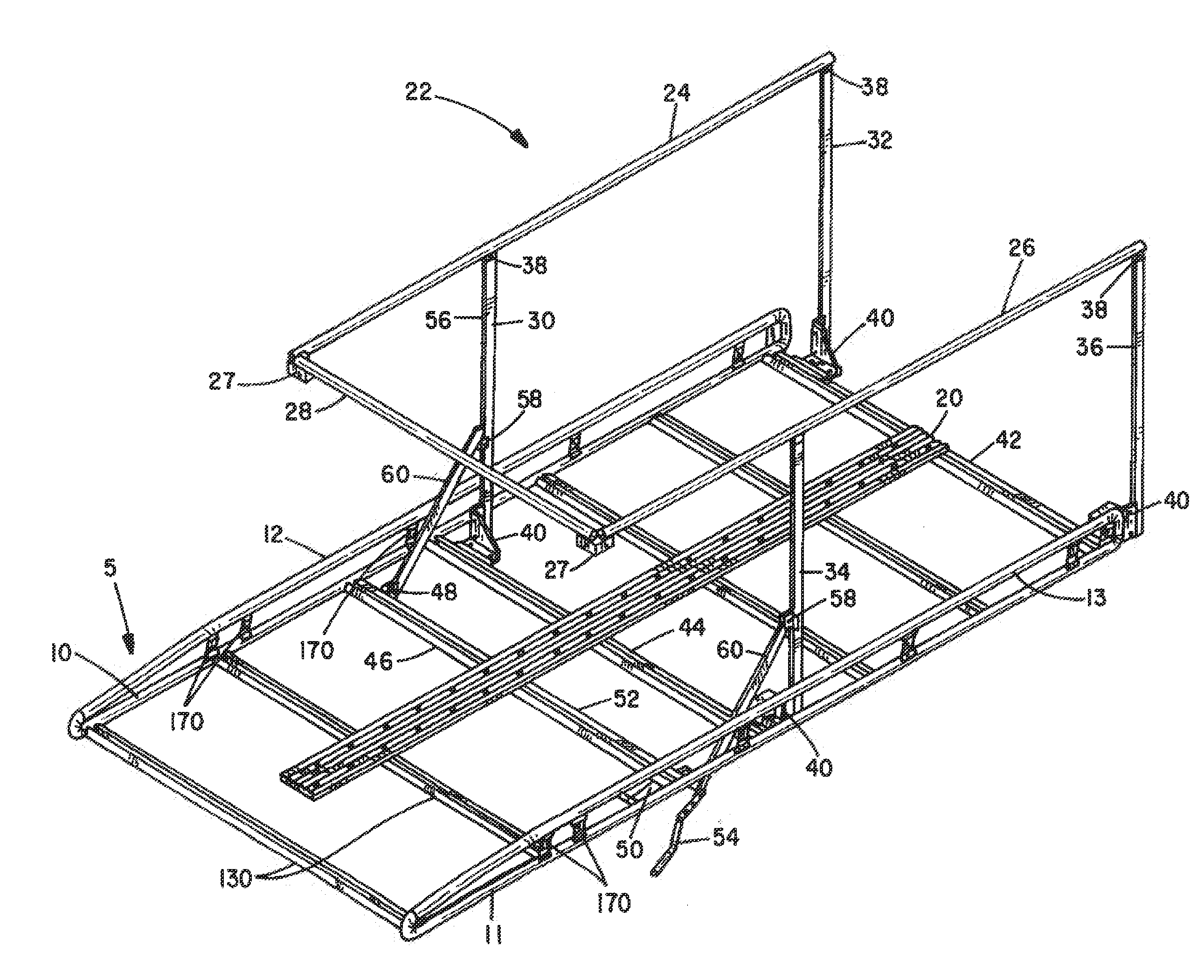
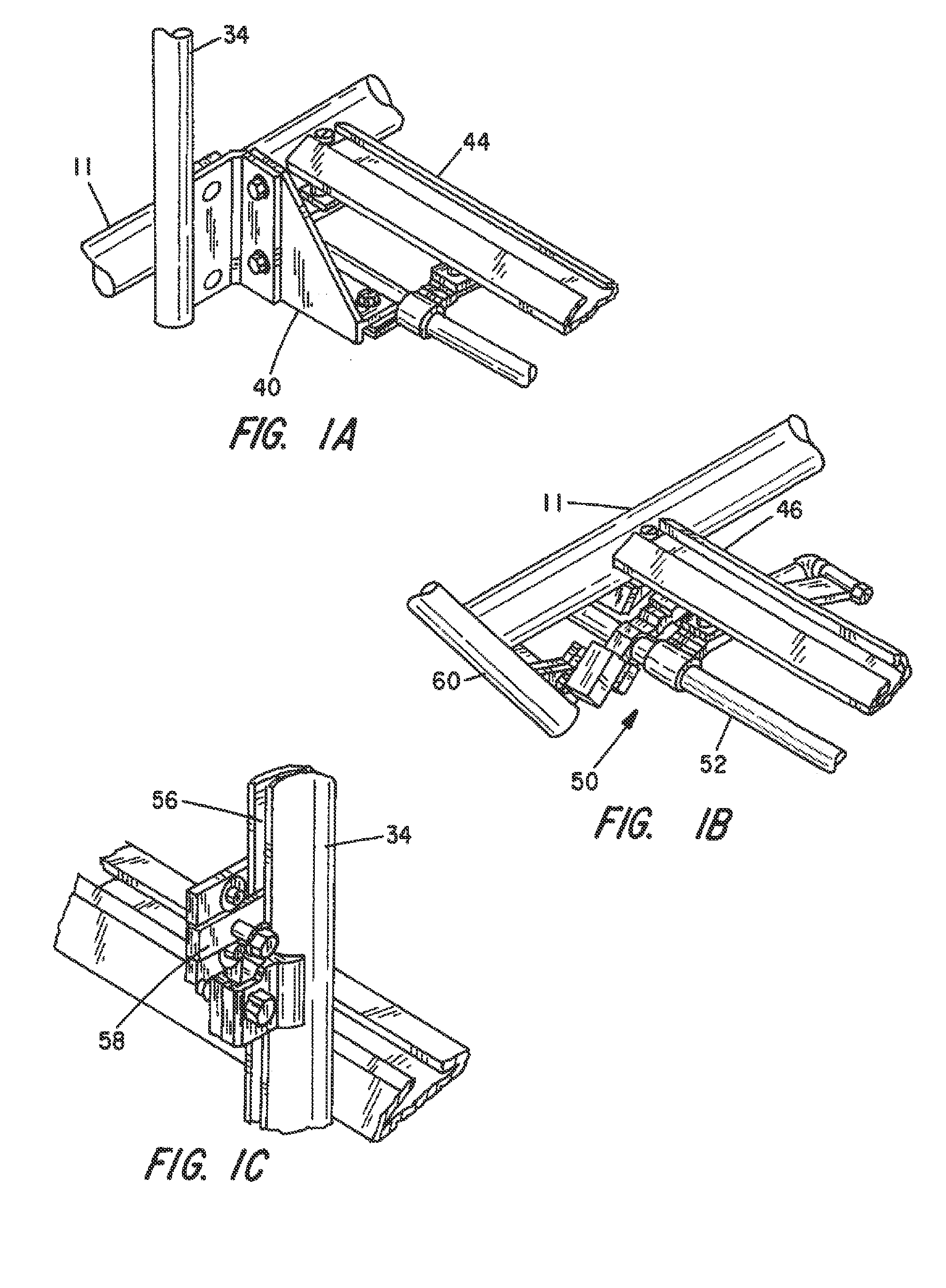
[0008]The present invention comprises a vehicle roof rack that can be securely clamped to the roof of a cargo van without any damage or alteration to the vehicle itself and which incorporates a collapsible handrail structure that can be readily raised and lowered by manual rotation of a crank arm. The roof rack preferably comprises the one described in Published PCT Application WO / 2009 / 126286 A1, the contents of which are hereby incorporated by reference as if fully set forth herein. The roof rack portion of the invention itself is an extremely strong, yet lightweight and easy to assemble on the roof of motor vehicles without any damage to the vehicle. It is fabricated for the most part using extruded aluminum tubing to create side members and crossbars for joining the side members to one another across the width dimension of the vehicle roof Each side member comprises a pair of elongated rails that are clamped together by a series of clamps that cooperate with attachment spines integrally formed with the rails. Attachment flanges forming a part of the extrusion on one rail on each side member facilitates attachment of the crossbar members thereto. The roof rack structure is adapted to be clamped to the vehicle's rain gutter using specially designed clamps that will not mar or distort the rain gutter at points of attachment.

Problems solved by technology

Likewise, electricians are frequently called upon to install wiring and lighting or other fixtures at elevated locations where ladder access is inconvenient.
Working from a vehicle rooftop location is not without risk, however.
Should a person stumble and fall, serious injury can result.
The Satchwell III U.S. Pat. No. 5,249,436 shows one such arrangement where a collapsible railing structure is bolted or otherwise affixed directly to the vehicle's roof, thus causing permanent damage to the vehicle at numerous points along either side of the vehicle's roof where railing balusters have been located.

Method used


Image

  • Vehicle roof rack with collapsible handrail assembly
  • Vehicle roof rack with collapsible handrail assembly
  • Vehicle roof rack with collapsible handrail assembly

Examples


Embodiment Construction

[0018]This description of the preferred embodiments is intended to be read in connection with the accompanying drawings, which are to be considered part of the entire written description of this invention. In the description, relative terms such as “lower”, “upper”, “horizontal”, “vertical”, “above”, “below”, “up”, “down”, “top” and “bottom” as well as derivatives thereof (e.g., “horizontally”, “downwardly”, “upwardly”, etc.) should be construed to refer to the orientation as then described or as shown in the drawings under discussion. These relative terms are for convenience of description and do not require that the apparatus be constructed or operated in a particular orientation. Terms such as “connected”, “connecting”, “attached”, “attaching”, “join” and “joining” are used interchangeably and refer to one structure or surface being secured to another structure or surface or integrally fabricated in one piece, unless expressively described otherwise.

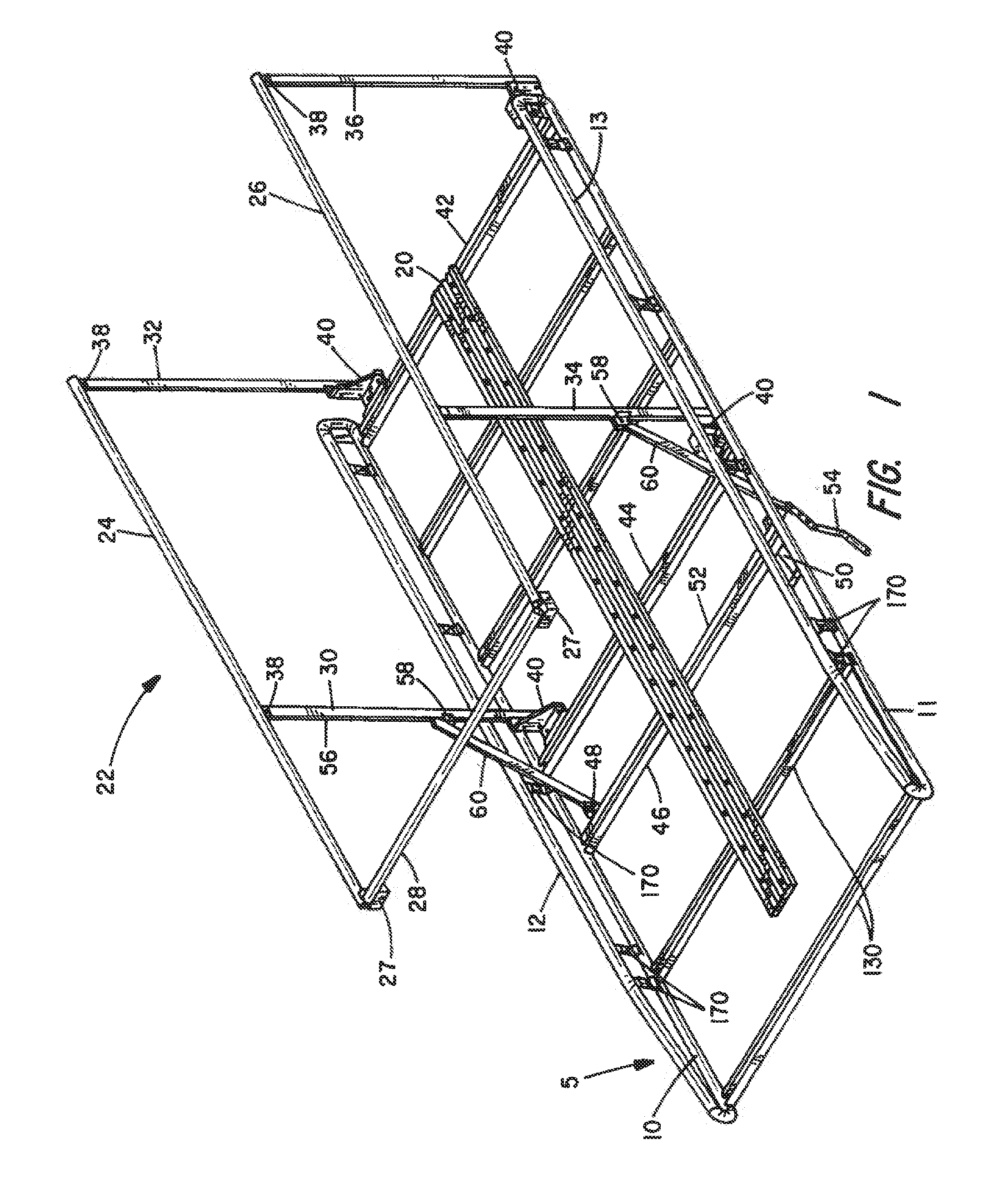
[0019]In FIG. 1, the roof rack...


PUM


Abstract

A safety railing for attachment to a vehicle roof mounted rack to reduce the likelihood of fall injuries to workers who have mounted to roof of the vehicle has a pair of side railings joined by a front railing and supported by balusters that pivotally attach to the roof rack. A crank operated mechanism is provided for shifting the balusters between an erect, vertical orientation and a collapsed orientation where the safety railing lies flat against the roof rack.

Description

CROSS REFERENCE TO RELATED APPLICATION:[0001]This application is a 371 of International application no. PCT / US2013 / 058887, filed Sep. 10, 2013, which claims priority to U.S. provisional application, Ser. No. 61 / 702,627, filed Sep. 18, 2012, the contents of which are hereby incorporated by reference.BACKGROUND OF THE INVENTION[0002]I. Field of the Invention[0003]This invention relates generally to safety equipment, and more particularly to a vehicle roof rack having a guardrail structure for use on cargo vans to preclude fall accidents to workers who may have occasion to stand on the vehicle's roof.[0004]II. Discussion of the Prior Art[0005]There are occupations that require workers to climb onto and stand on the roof of a motor vehicle, such as cargo vans and the like. For example, video news photographers frequently mount the roof of their vehicle to obtain recordings in a crowd scene. Likewise, electricians are frequently called upon to install wiring and lighting or other fixture...

Claims


Application Information

Patent Timeline
Patent Type & Authority Applications(United States)
IPC IPC(8): B60R9/058B60R3/00B60R9/045
CPCB60R9/058B60R3/005B60R9/045
Inventor LEVI, AVRAHAM Y.
Owner ROM ACQUISITION CORP
Why Eureka
Try Eureka