Railway vehicle brake disc

a brake disc and vehicle technology, applied in the field of brake discs, can solve the problems of reducing the cooling performance of the brake disc, stressing the fastening bolt, and raising the aerodynamic noise of the brake disc during the running at a high speed, so as to improve the durability of the brake disc including that of the fastening bolt, and reduce the aerodynamic nois

Active Publication Date: 2015-09-03
NIPPON STEEL CORP
View PDF2 Cites 14 Cited by
  • Summary
  • Abstract
  • Description
  • Claims
  • Application Information

AI Technical Summary

Benefits of technology

[0027]According to the railway vehicle brake disc of the present invention, since the groove is formed along the circumferential direction in the fin section having the bolt hole formed therein, the aerodynamic noise raised during the running at a high speed can be reduced, the cooling performance of the brake disc at the time of braking can be improved, and furthermore the durability of the brake disc including that of a fastening bolt can be improved.

Problems solved by technology

The gas stream remarkably appears in a high speed running state of more than 300 km / h, and induces noises called aerodynamic noise.
However, a problem of lower cooling performance of the brake disc at the time of braking with suppression of the gas stream by the rib becomes apparent.
In addition, in a case where an emergency brake is used in the high speed running state, for example, as described in Patent Literatures 2 and 3, deformation of the brake disc associated with thermal expansion, and a stress load on a fastening bolt due to the deformation increase, and it becomes difficult to secure the durability of the brake disc and the bolt.

Method used


Image

  • Railway vehicle brake disc
  • Railway vehicle brake disc
  • Railway vehicle brake disc

Examples


first embodiment

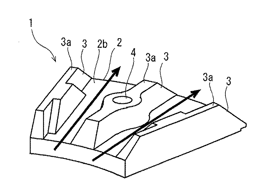
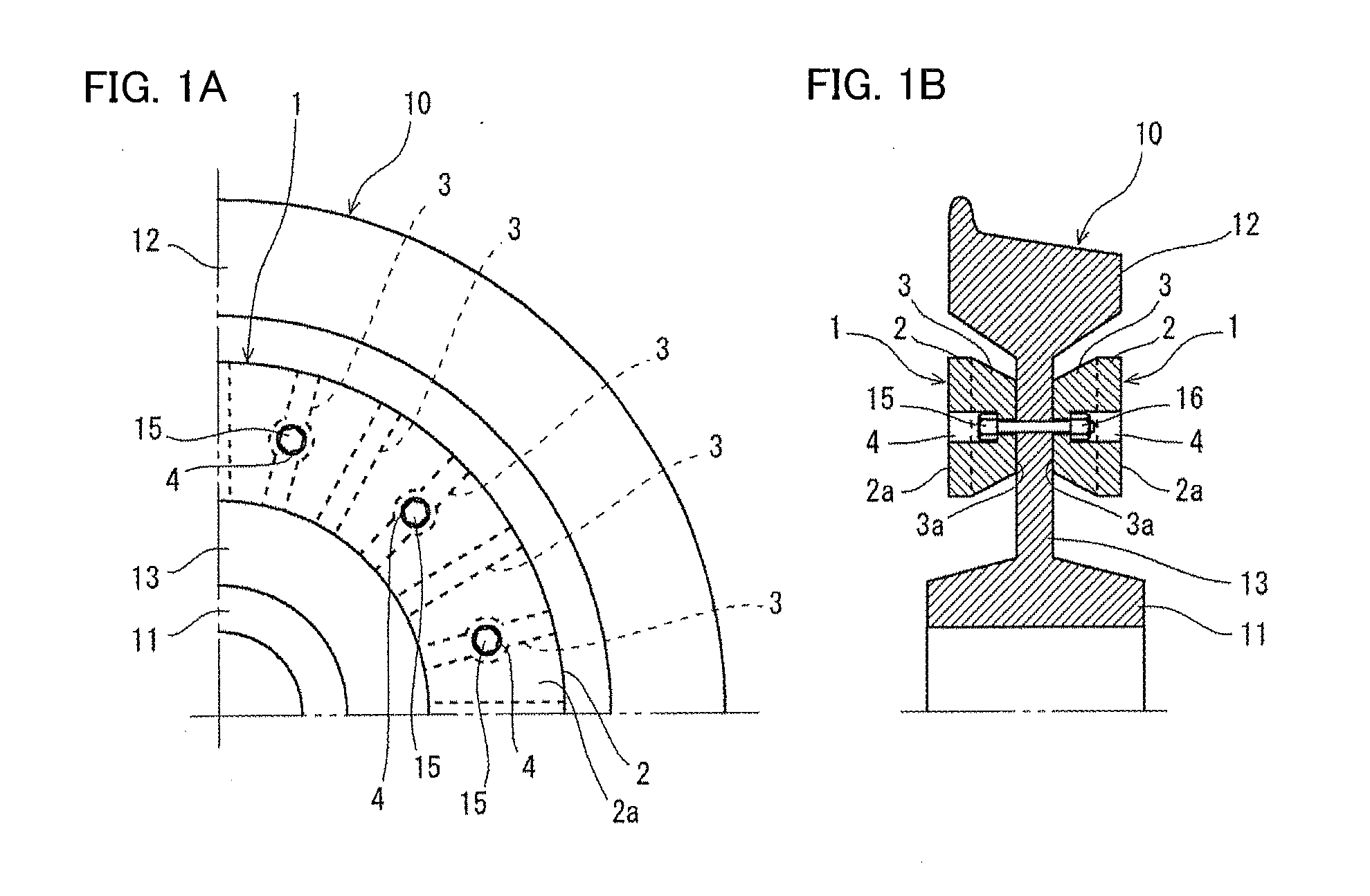
[0042]FIGS. 9A to 9C are schematic views illustrating an example of a configuration of a railway vehicle brake disc according to a first embodiment of the present invention; FIG. 9A illustrates a partial perspective view when viewed from a rear surface side; FIG. 9B illustrates a partial plan view in a rear surface view; and FIG. 9C illustrates a partial cross-sectional view taken along the radial direction. Incidentally, in FIGS. 9A and 9B, a 1 / 12 circular portion of the brake disc is representatively illustrated.

[0043]As illustrated in FIGS. 9A to 9C, a brake disc 1 of the first embodiment comprises a donut-shaped disc section 2 having a sliding surface on a front surface 2a side. In a rear surface 2b of the disc section 2, a plurality of fin sections 3 is convexly provided in a radial pattern. A bolt hole 4 passing through the disc section 2 is formed almost at a central position in the radial direction in some of the plurality of fin sections 3.

[0044]In a fin section 3 having th...

second embodiment

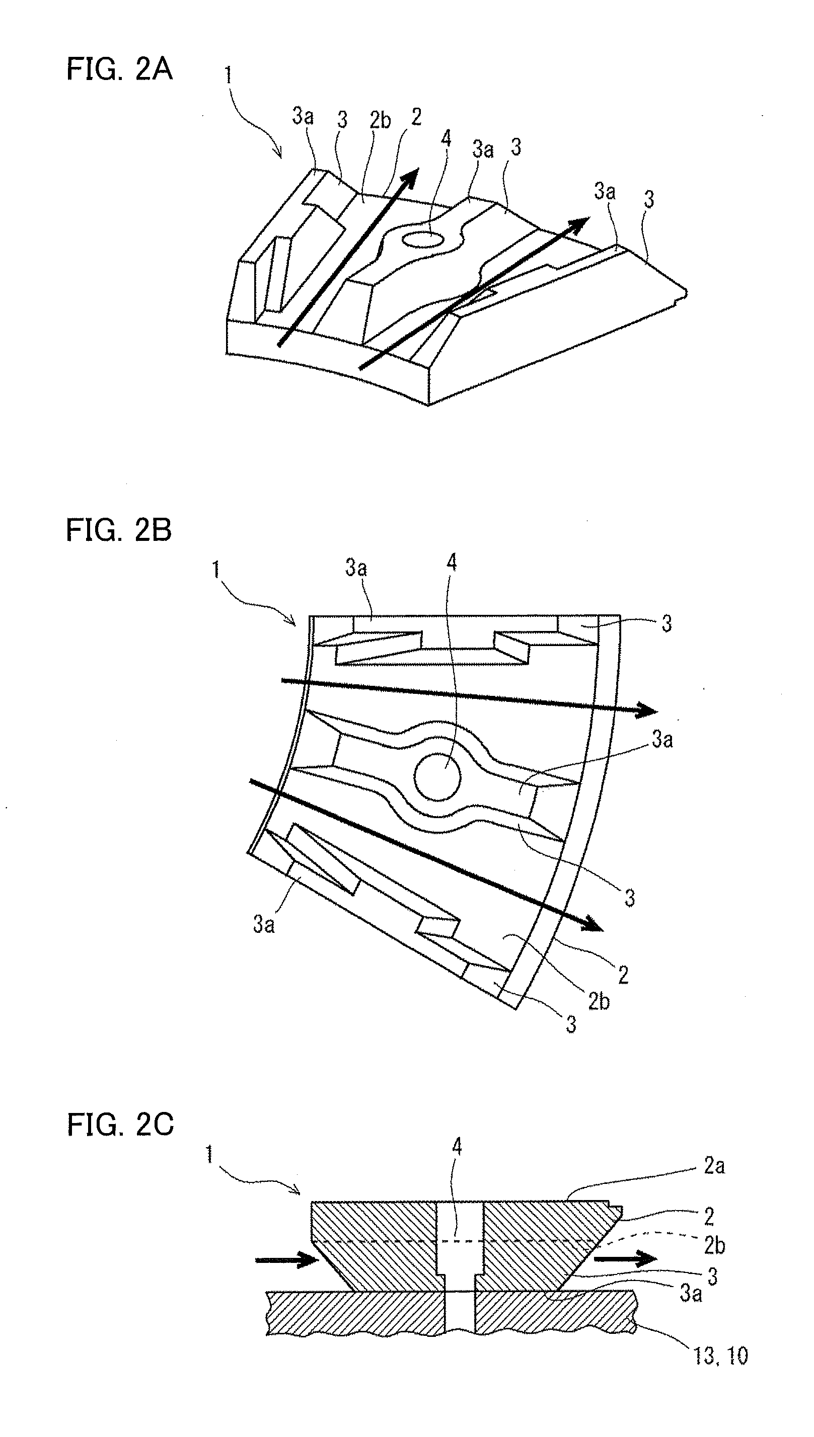
[0065]FIGS. 4A to 4C are schematic diagrams illustrating an example of a configuration of a railway vehicle brake disc according to a second embodiment of the present invention; FIG. 4A illustrates a partial perspective view when viewed from a rear surface side; FIG. 4B illustrates a partial plan view in a rear surface view; and FIG. 4C illustrates a partial cross-sectional view taken along the radial direction. Incidentally, in FIGS. 4A and 4B, a 1 / 12 circular portion of the brake disc is representatively illustrated.

[0066]As illustrated in FIGS. 4A to 4C, a brake disc 1 of the second embodiment includes a donut-shaped disc section 2 having a sliding surface on a front surface 2a side. In a rear surface 2b of the disc section 2, a plurality of fin sections 3 is convexly provided in a radial pattern. A bolt hole 4 passing through the disc section 2 is formed almost at a central position in the radial direction in some of the plurality of fin sections 3.

[0067]In a fin section 3 havin...

third embodiment

[0093]FIGS. 7A to 7C are schematic views illustrating an example of a configuration of a railway vehicle brake disc according to a third embodiment of the present invention; FIG. 7A illustrates a partial perspective view when viewed from a rear surface side; FIG. 7B illustrates a partial plan view in a rear surface view; and FIG. 7C illustrates a partial cross-sectional view taken along the radial direction. Incidentally, FIGS. 7A and 7B representatively illustrate a 1 / 12 circular portion of the brake disc in a similar manner to FIGS. 4A and 4B.

[0094]The brake disc of the third embodiment illustrated in FIGS. 7A to 7C has the same basic configuration as the brake disc of the second embodiment illustrated in FIGS. 4A to 4C, but is different from the brake disc of the second embodiment in the following points. That is, as illustrated in FIGS. 7A to 7C, in a fin section 3 of the third embodiment, a width t2 in the circumferential direction of an area on an outer peripheral side is made...


PUM


Abstract

A railway vehicle brake disc which can reduce aerodynamic sound raised high speed running, improve cooling performance during braking, and improve durability comprises a donut-shaped disc section having a sliding surface on a front surface side, a plurality of fin sections, each convexly provided in a rear surface of the disc section in a radial pattern, and a bolt hole passing through the disc section and the fin section. The disc section is mounted on a wheel in a state where the fin sections contact a plate section of the wheel using a bolt inserted into the bolt hole. The fin section has a groove formed along a circumferential direction in at least one of an area on an inner peripheral side and an area on an outer peripheral side of the bolt hole when viewed in a radial direction of the disc section.

Description

TECHNICAL FIELD[0001]The present invention relates to a brake disc which is a key component of a braking device in a railway vehicle, and particularly to a railway vehicle brake disc in which a disc section serving as a sliding surface is fastened to a wheel with a bolt.BACKGROUND ART[0002]As the braking device of the railway vehicle, a disc brake excellent in braking performance is frequently used with increase in speed and size of a vehicle. In the disc brake, a brake disc is mounted on a wheel by being fastened with a bolt, a braking force due to frictional resistance is generated by a brake lining pushed against a sliding surface of the brake disc, and thus the rotation of the wheel is braked to regulate a speed of the vehicle.[0003]FIGS. 1A and 1B are diagrams schematically illustrating a mounting structure of a typical railway vehicle brake disc onto a wheel; FIG. 1A illustrates a plan view of a ¼ circular portion in a front surface view; and FIG. 1B illustrates a cross-sectio...

Claims


Application Information

Patent Timeline
Patent Type & Authority Applications(United States)
IPC IPC(8): F16D65/12F16D65/00B61H5/00F16D65/847
CPCF16D65/124F16D65/128B61H5/00F16D65/0006F16D65/847F16D65/12F16D2065/1328
Inventor NOGAMI, HIROSHIADACHI, GOASABE, KAZUTAKASAKAGUCHI, ATSUSHITAMURA, KENJIKATO, TAKANORI
Owner NIPPON STEEL CORP
Why Eureka
Try Eureka