Electronic device, electronic apparatus, and moving object
a technology of electronic equipment and moving objects, applied in the direction of pulse manipulation, pulse technique, instruments, etc., can solve the problem of difficult circuit miniaturization and achieve the effect of reducing current consumption
- Summary
- Abstract
- Description
- Claims
- Application Information
AI Technical Summary
Benefits of technology
Problems solved by technology
Method used
Image

Examples
first embodiment
Basic Configuration of Electronic Device
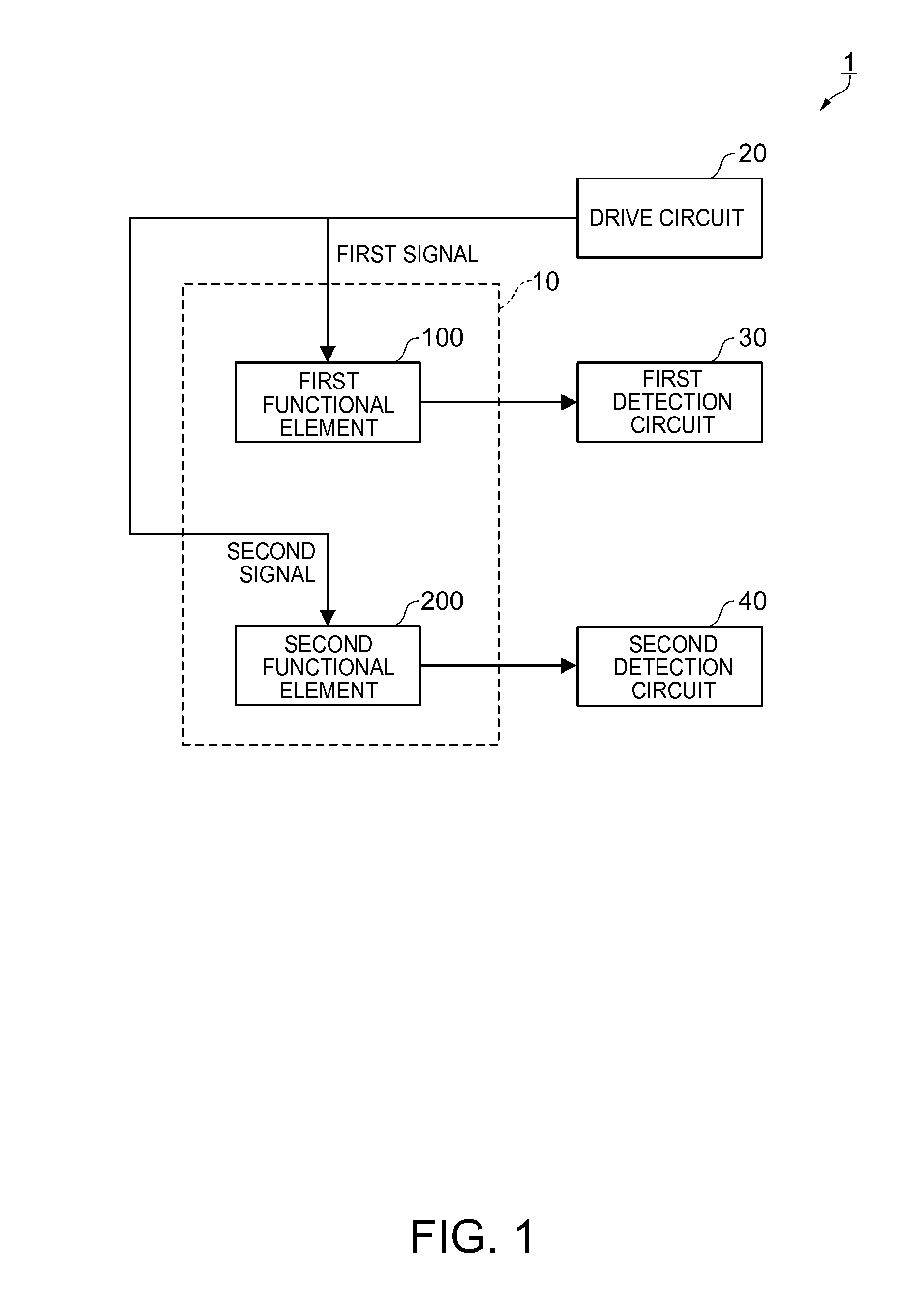
[0047]The basic configuration of a composite sensor as an electronic device according to the first embodiment will be explained with reference to FIGS. 1, 2A, and 2B. FIG. 1 is a block diagram showing a schematic configuration of the composite sensor according to the first embodiment. As shown in FIG. 1, the composite sensor 1 according to the first embodiment is provided with a sensor element section 10, a drive circuit 20 as a signal generation section, a first detection circuit 30, and a second detection circuit 40.
[0048]The sensor element section 10 according to the first embodiment includes an angular velocity sensor (a gyro sensor) element 100 as a first functional element, and an acceleration sensor element 200 as a second functional element. In the present embodiment, the explanation will be presented taking the case, in which both of the angular velocity sensor element 100 and the acceleration sensor element 200 are each a capacitance...
second embodiment
Basic Configuration of Electronic Device
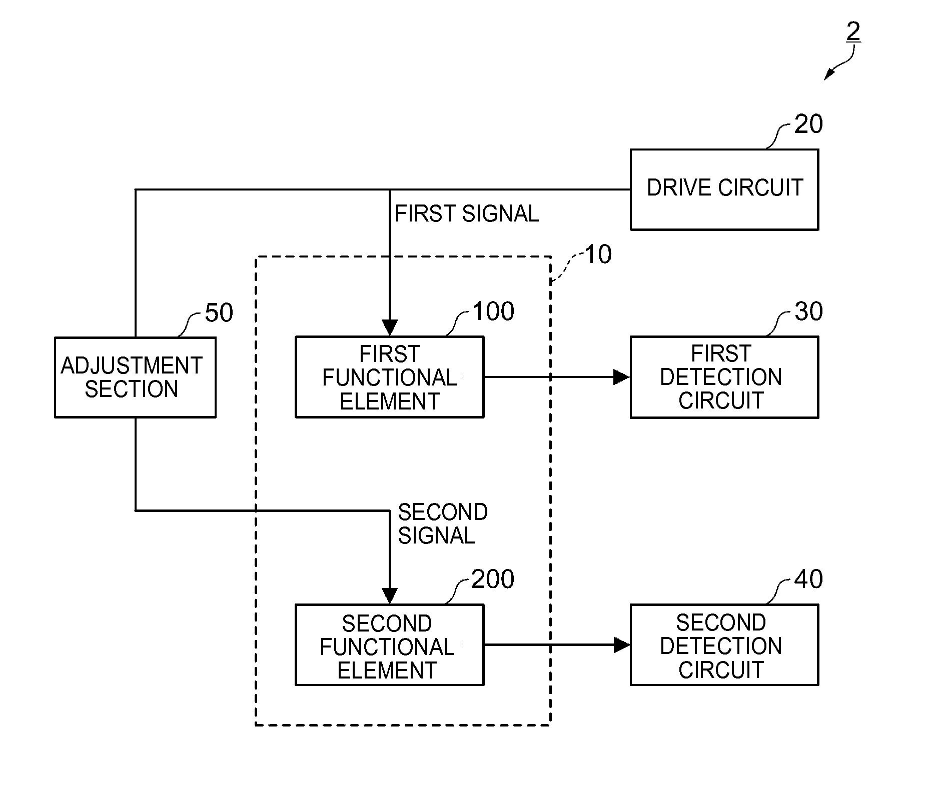
[0148]The basic configuration of a composite sensor as an electronic device according to a second embodiment will be explained with reference to FIG. 7. FIG. 7 is a block diagram showing a schematic configuration of the composite sensor according to the second embodiment. The composite sensor according to the second embodiment has substantially the same configuration as the configuration in the first embodiment except the point that an adjustment section is further provided. Here, the difference from the first embodiment will be explained. The constituents common to the first embodiment and the present embodiment are denoted with the same reference symbols, and the explanation thereof will be omitted.
[0149]As shown in FIG. 7, the composite sensor 2 according to the second embodiment is provided with the sensor element section 10, the drive circuit 20, the first detection circuit 30, the second detection circuit 40, and the adjustment section 5...
third embodiment
Basic Configuration of Electronic Device
[0153]The basic configuration of a composite sensor as an electronic device according to a third embodiment will be explained with reference to FIGS. 8 and 9. FIG. 8 is a block diagram showing a schematic configuration of the composite sensor according to the third embodiment. The composite sensor according to the third embodiment has substantially the same configuration as the configuration in the first embodiment except the point that a third functional element and a third detection circuit are further provided. Here, the difference from the first embodiment will be explained. The constituents common to the first embodiment and the present embodiment are denoted with the same reference symbols, and the explanation thereof will be omitted.
[0154]As shown in FIG. 8, the composite sensor 3 according to the third embodiment is provided with a sensor element section 10A, the drive circuit 20, the first detection circuit 30, the second detection ci...
PUM
 Abstract
Description
Claims
Application Information
 - R&D Engineer
- R&D Manager
- IP Professional
- Industry Leading Data Capabilities
- Powerful AI technology
- Patent DNA Extraction
Browse by: Latest US Patents, China's latest patents, Technical Efficacy Thesaurus, Application Domain, Technology Topic.
© 2024 PatSnap. All rights reserved.Legal|Privacy policy|Modern Slavery Act Transparency Statement|Sitemap