Moving image encoding device

a technology of moving image and encoding device, which is applied in the direction of instruments, computing, electrical apparatus, etc., can solve the problems of increasing the load on the server device for transferring the drawing data to the terminal device, affecting so as to achieve the effect of increasing the legibility of characters

Active Publication Date: 2015-09-03
NEC CORP
View PDF0 Cites 6 Cited by
  • Summary
  • Abstract
  • Description
  • Claims
  • Application Information

AI Technical Summary

Benefits of technology

[0035]According to the present invention, it is possible to increase the legibility of characters in a video image in a short frame period.

Problems solved by technology

Therefore, when the amount of drawing data to be processed increases or when the number of terminal devices connected to the server device increases, the load on the server device for transferring the drawing data to the terminal devices increases, and problems such as deterioration of response time and considerable limitation of the number of connected terminal devices arise.
When irreversible transformation such as quantization is used in data compression, the quality of an image decoded on the reception side may deteriorate as compared with the quality of the original image on the transmission side.
Also, in a case where a data loss or a transmission error occurs in a communication path and so on, the quality of an image on the reception side may deteriorate.
In a case where the upper limit of the amount of outputted codes per frame is fixed, with respect to a frame in which the area of an updated region is large, it is difficult to encode the updated region with high quality, and therefore, there is no choice but to encode the updated region with low quality.
However, in a case where an updated region is large in size and includes character regions at the high ratio, it is impossible, when the amount of all codes of the updated region exceeds the upper limit of an allowable code amount per frame, to achieve a high image quality in all of the character regions.
As a result, in the same manner as mentioned above, a case where a character region is left low-quality for a long time occurs, and the legibility of characters in a video image decreases.

Method used


Image

  • Moving image encoding device
  • Moving image encoding device
  • Moving image encoding device

Examples


first exemplary embodiment

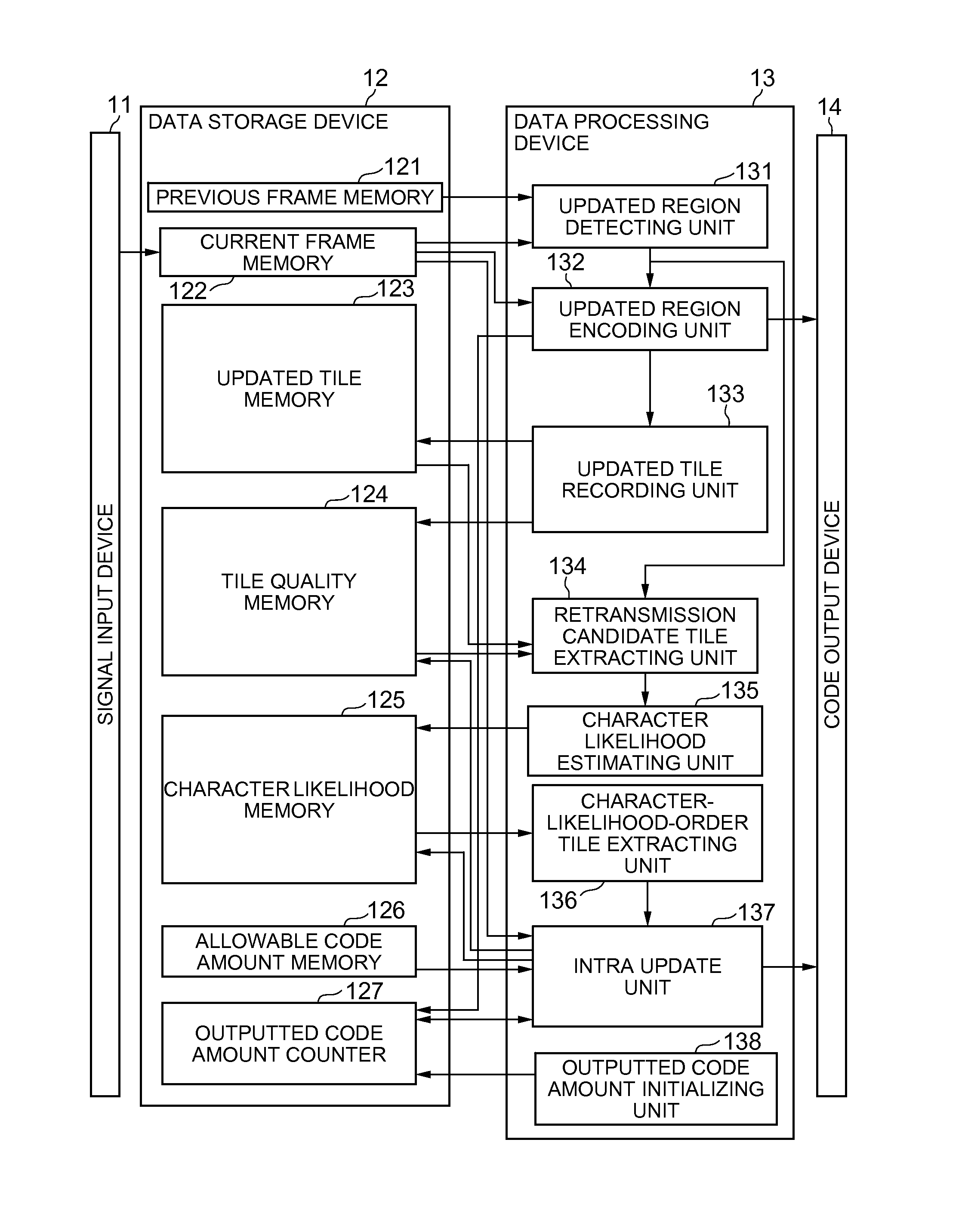
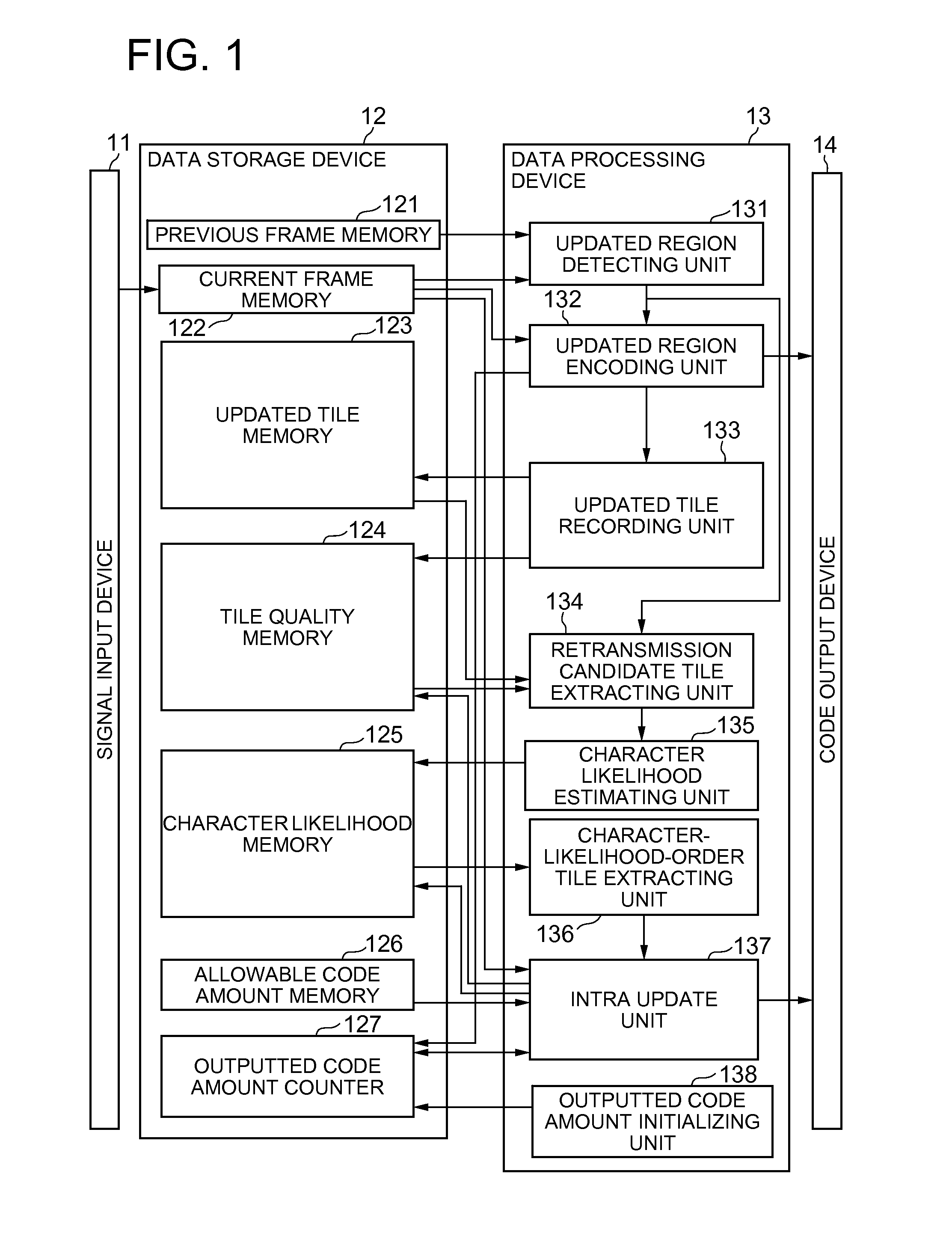
[0044]Referring to FIG. 1, a first exemplary embodiment of the present invention includes a signal input device 11, a data storage device 12, a data processing device 13 which operates under program control, and a code output device 14.

Description of Configuration

[0045]The signal input device 11 is a device for inputting a video signal. For example, the signal input device 11 captures analog or digital signals of a color video image on a display screen of a computer which is not shown in the drawings, and stores the result into the data storage device 12. The captured video signal of one screen is referred to as a frame or screen data.

[0046]The code output device 14 is configured by a storage device like a magnetic disk device, a communication device or the like, which stores or transmits code information obtained by encoding by the data processing device 13.

[0047]The data storage device 12 includes a previous frame memory 121, a current frame memory 122, an updated tile memory 123,...


PUM


Abstract

An updated region encoding unit detects an updated region in a frame of an inputted image signal and encodes the updated region. A retransmission candidate tile extracting unit extracts from within a screen a tile which does not belong to an updated region in a current frame and which is a partial region transmitted after encoded with a quality equal to or less than a first quality. A character likelihood estimating unit, with respect to a tile extracted by the retransmission candidate tile extracting unit, calculates a likelihood value indicating likelihood that the tile is a character region. A character-likelihood-order intra update unit selects a tile in decreasing order of the likelihood value from among tiles extracted by the retransmission candidate tile extracting unit, and encodes the tile with a second quality which is higher than the first quality and transmits the result.

Description

TECHNICAL FIELD[0001]The present invention relates to a moving image encoding device. More specifically, the present invention relates to a moving image encoding device which encodes a video image on a computer screen, a moving image encoding method, and a program.BACKGROUND ART[0002]In recent years, for the purpose of achieving prevention of leakage of information from a computer terminal device and facilitation of management of applications on the terminal, a thin client system has been introduced. A thin client system makes a server device execute all applications inputted into, outputted from and displayed at a terminal device and also makes the server device manage all generated files relating to the execution.[0003]In such a thin client system, drawing data of an application program executed by the server device is transferred to a client terminal device through a network such as a LAN, and displayed on the screen of the terminal device. Therefore, when the amount of drawing d...

Claims


Application Information

Patent Timeline
Patent Type & Authority Applications(United States)
IPC IPC(8): H04N19/107H04N19/507H04N19/17
CPCH04N19/107H04N19/507H04N19/17
Inventor TAKADA, JUN
Owner NEC CORP
Why Eureka
Try Eureka