
Detector arrangement in connection with a mobile work machine

a technology of detector arrangement and mobile work machine, which is applied in the direction of transportation items, transportation devices, vehicles carrying long loads, etc., can solve the problems of angular value distortion, harm sensor arrangement, and determination of angular position by using different conventional inclination detectors

Active Publication Date: 2015-09-10
PONSSE
View PDF2 Cites 14 Cited by
  • Summary
  • Abstract
  • Description
  • Claims
  • Application Information

AI Technical Summary

Benefits of technology

The present invention provides a better way to detect and track the position and motion of different parts of a mobile work machine. This is done through a detector arrangement that includes sensors in each part that can measure different variables and a data processing system that can use this information to determine the position and motion of each part in relation to a fixed reference point. This allows for more accurate tracking of the movement of the work machine and helps to improve its overall performance and efficiency.

Problems solved by technology

However, all known solutions present problems that are usually caused by the measuring methods and devices used as well as the operating manners and operating conditions of the forest work units and / or the compatibility thereof.
In addition, environmental conditions, such as great variation in outside temperature as well as moisture and impurities, may harm sensors arranged particularly in connection with the structures of a forest machine or control electronics of the machine.
Determination of an angular position by using different conventional inclination detectors presents various problems.
A problem with detectors based on an acceleration sensor is that other accelerations, in addition to gravitational acceleration, directed at the sensor cause distortion in an angular value.
Consequently, errors caused by non-idealities of the measurement and measuring arrangements accumulate during use in the angular position determination based on angular velocity.

Method used


Image

  • Detector arrangement in connection with a mobile work machine
  • Detector arrangement in connection with a mobile work machine
  • Detector arrangement in connection with a mobile work machine

Examples


Embodiment Construction

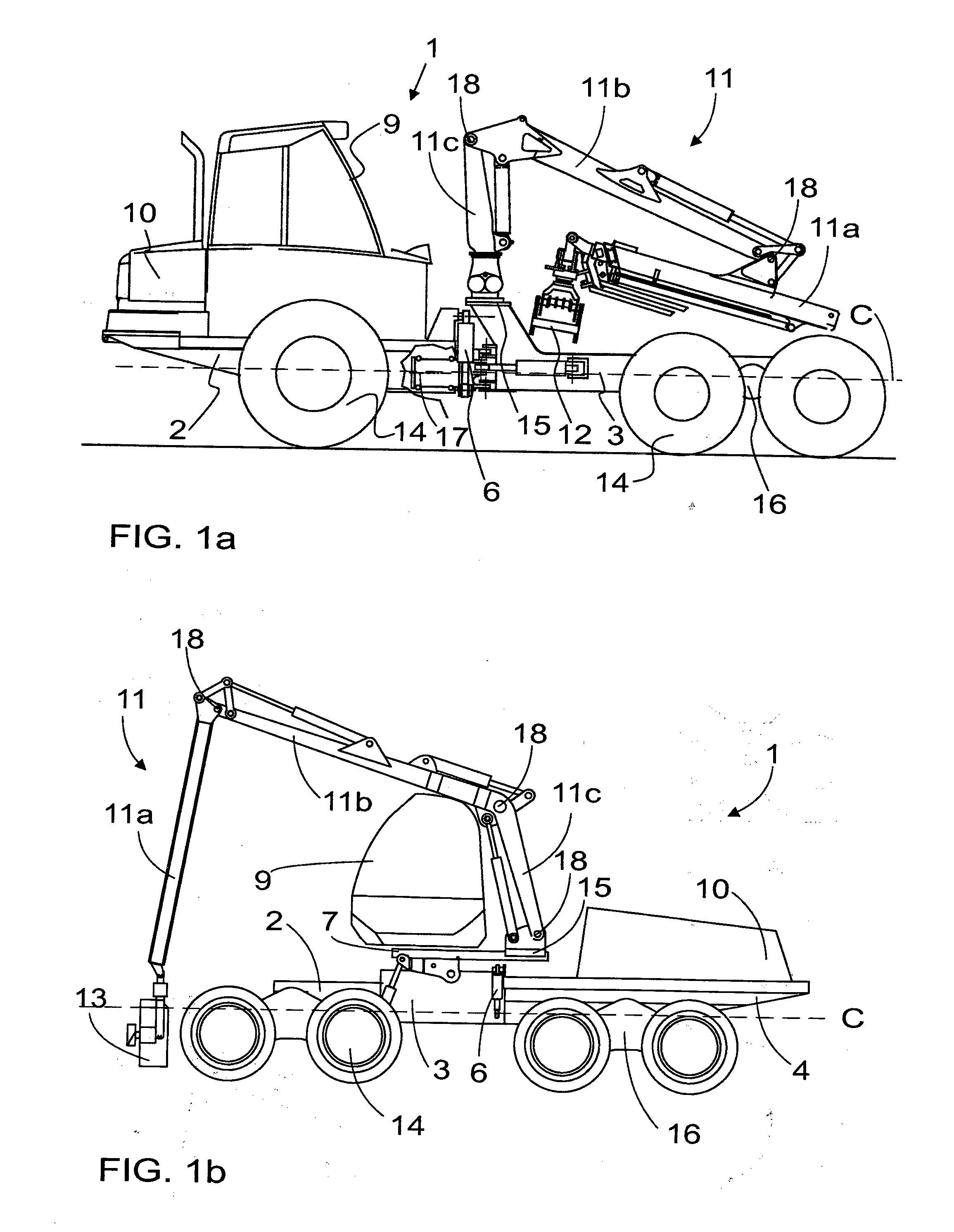
[0031]FIGS. 1a and 1b schematically show two forest work units as examples of mobile work machines 1. In the figures, like reference numerals identify parts of like structure and / or purpose. A mobile work machine 1, such as a forest work unit, a forwarder in the case of FIG. 1a and a harvester in the case of FIG. 1b, may comprise frame parts, in the case of FIG. 1a two frame parts 2, 3 joined together by articulation. Typically, the forest work unit 1 comprises a control cabin 9 arranged in one frame part 2, 3, 4, at least one power source 10, which is arranged in the same frame part 2, 3, 4 as the control cabin or in a different frame part, for generating power to move and control the forest work unit and / or the tools therein. The forest work unit 1 further comprises tools, such as a boom assembly 11, which may comprise one or more boom sections 11a, 11b, and 11c that may have been pivoted by joints 18 to one another and / or the frame part, typically arranged in one or more frame pa...


PUM


Abstract

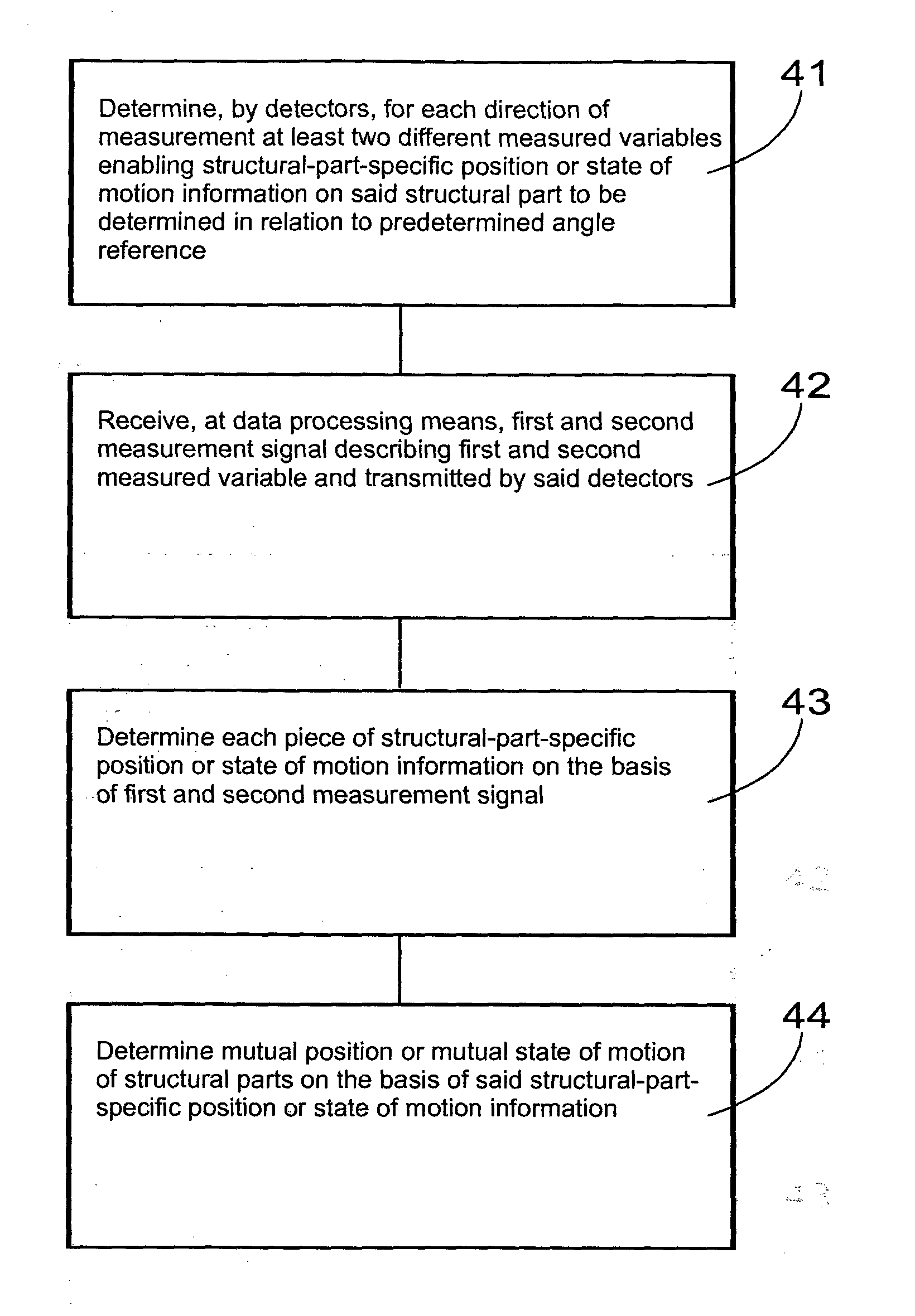
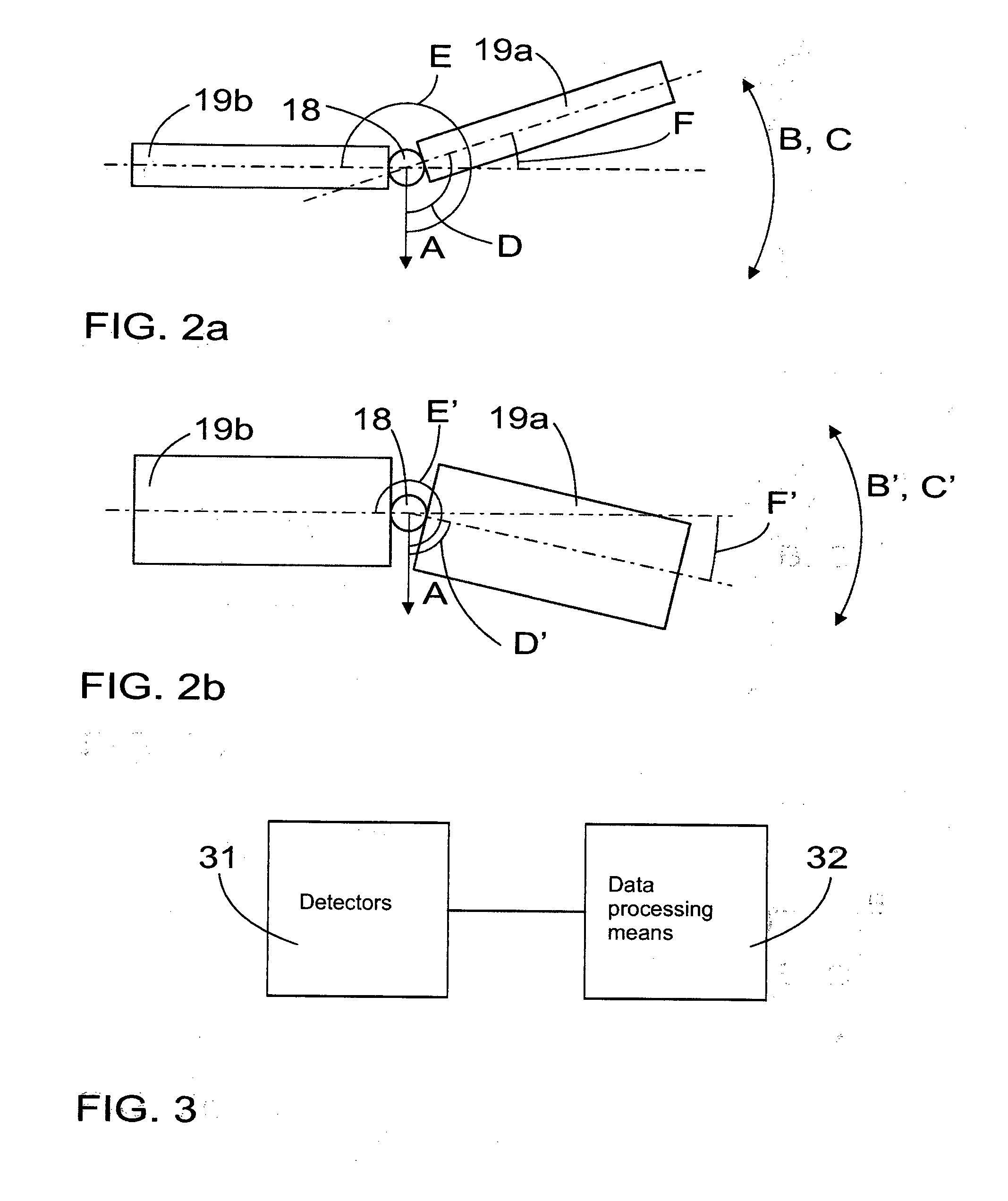
The invention relates to a detector arrangement and method for determining a mutual position or a mutual state of motion of at least two structural parts of a mobile work machine. The arrangement comprises detectors configurable to determine at least in one direction of measurement at least two different measured variables in order to determine at least structural-part-specific position or state of motion information for each direction of measurement. The arrangement further comprises a data processing means for receiving measurement signals describing measured variables as well as for determining a mutual position or state of motion of the structural parts on the basis of the structural-part-specific position or state of motion information.

Description

BACKGROUND[0001]The invention relates to a detector arrangement in connection with a mobile work machine.[0002]The invention further relates to a method of determining a mutual position or a mutual state of motion of at least two structural parts of a mobile work machine.[0003]Determination of an absolute or a relative position of structural parts of mobile work machines, such as forest work units, is necessary e.g. for controlling the machines, improving the operator's work ergonomics, ensuring safe and efficient working, and managing forces to which the machine is subjected. Various solutions are known for determining the position of the structural parts. These solutions are often based on contact and / or mechanical connection, such as articulation angle measurements between two structural parts by means of a rotation angle sensor to be installed directly in a joint, such as a resolver, or, alternatively, e.g. measurements of a position of linear movement of a linear actuator contr...

Claims


Application Information

Patent Timeline
Patent Type & Authority Applications(United States)
IPC IPC(8): G01D1/16G01P15/00G01P3/00
CPCG01D1/16G01P15/00G01P3/00A01G23/00B60D1/30B60D1/62B60D5/00B60P1/045B60P3/41B62D53/00E02F9/2033
Inventor INBERG, JUHAKIVI, ALEKSI
Owner PONSSE
Learn More