Direct field acoustic testing in a semi-reverberant enclosure

a semi-reverberant enclosure and acoustic testing technology, applied in the field of vibration testing, can solve the problems of increasing the risk of failure of input power, reducing the amount of testing, and requiring substantial cost and effort to transport, deploy and tear down

Active Publication Date: 2015-09-10
MSI DFAT
View PDF24 Cites 149 Cited by
  • Summary
  • Abstract
  • Description
  • Claims
  • Application Information

AI Technical Summary

Benefits of technology

[0011]Embodiments hereof also include a direct field acoustic testing system contained within an acoustic enclosure offering acoustic isolation from the surrounding environment and pre-determined reverberant characteristics, at least four control microphones, a multiple-input-multiple-output (MIMO) vibration control system having at least four inputs and at least four separately controllable controller outputs, at least four separately driven groups of acoustical transducers and a signal modifier and combiner for modifying and directing combinations of controller output signals to each of the at least four groups of acoustical transducers wherein at least two of the separately controllable controller output signals are each directed to at least two groups of acoustical transducers in such a way as to provide an approximately even distribution of said at least two separately controllable controller output signals within the test environment so as to provide an acoustic field having a higher degree of spatial uniformity.

Problems solved by technology

However, to achieve the high acoustic levels required for many spacecraft tests very large arrays of acoustic transducers and associated amplification delivering substantial electrical input power are required.
Substantial cost and effort is required to transport, deploy and teardown said equipment and the high levels of input power increase the risk of failure.
Additionally, it is difficult to scale down the amount of equipment required for testing small objects such as components leading to a relatively high cost for direct field acoustic testing of such smaller items.
However, as is well known to those with skill in the art the narrow band phenomena of enclosure resonances, standing waves and wave interference patterns are the greatest problem for field uniformity in an enclosure.
However, as discussed in the '870 application SISO methods do not produce good narrow band uniformity and have no ability to control coherence.

Method used


Image

  • Direct field acoustic testing in a semi-reverberant enclosure
  • Direct field acoustic testing in a semi-reverberant enclosure
  • Direct field acoustic testing in a semi-reverberant enclosure

Examples


Embodiment Construction

[0018]Embodiments hereof are now described with reference to the figures in which like reference characters / numbers indicate identical or functionally similar elements. While specific configurations and arrangements are discussed, it should be understood that this is done for illustrative purposes only. A person skilled in the relevant art will recognize that other configurations and arrangements can be used without departing from the spirit and scope of the invention.

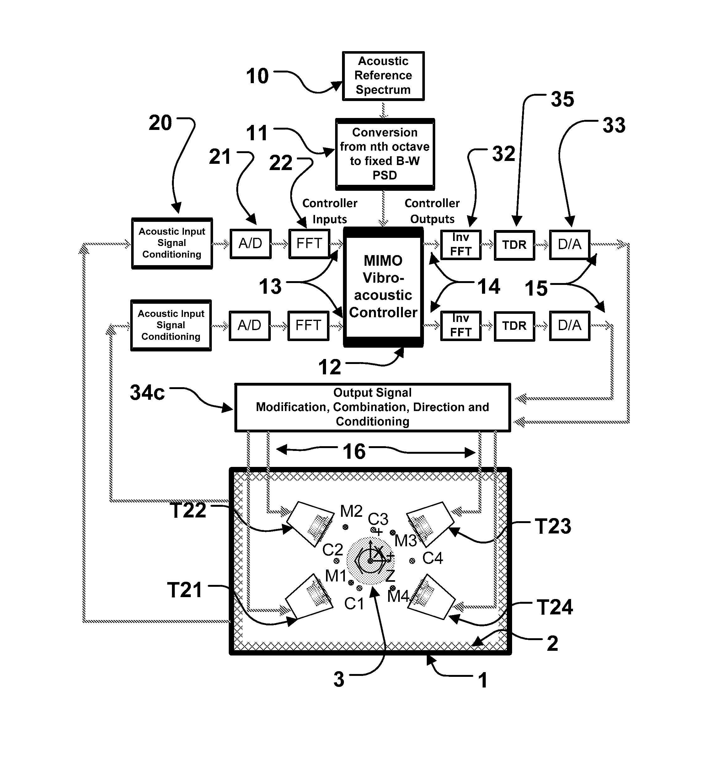
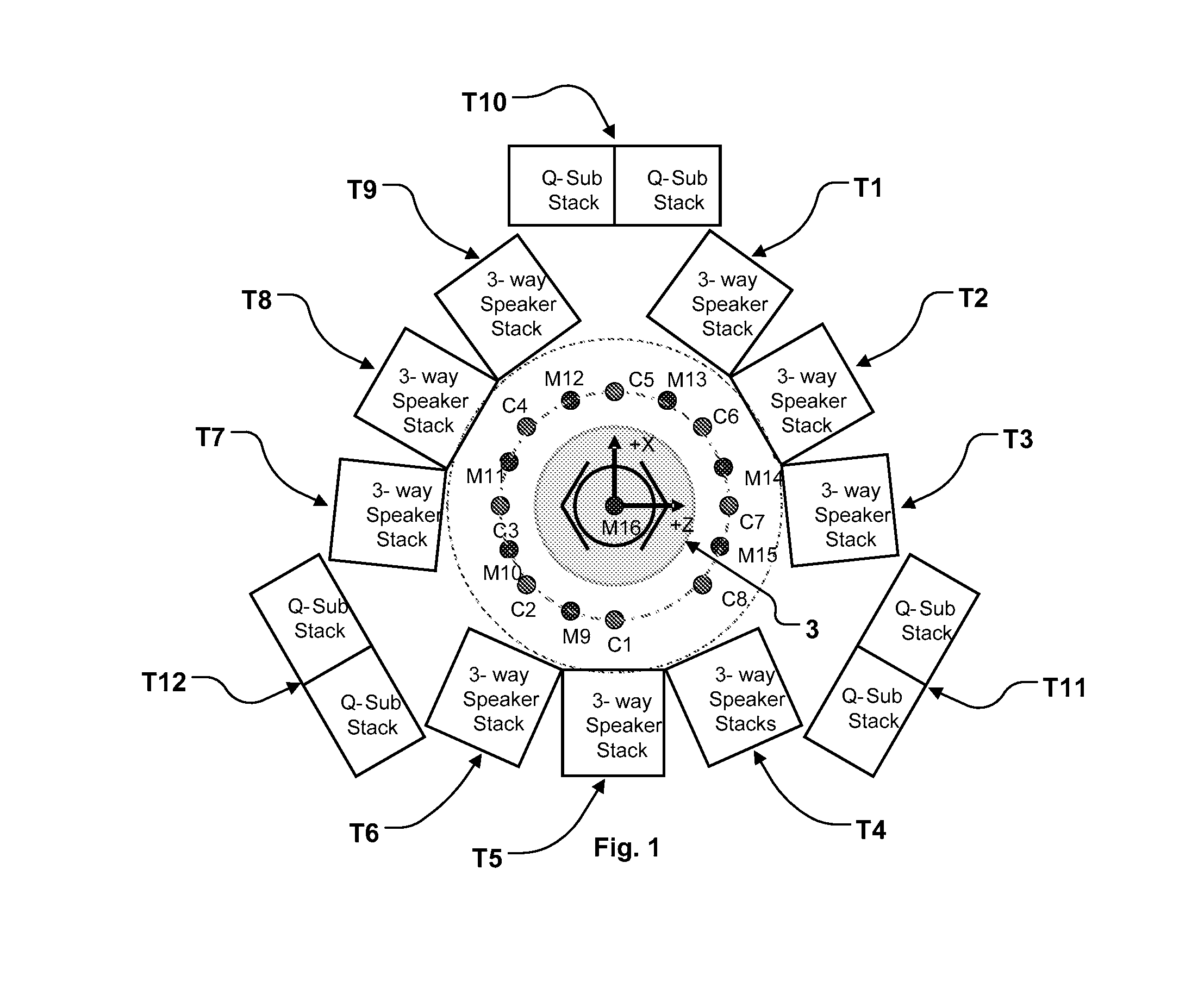
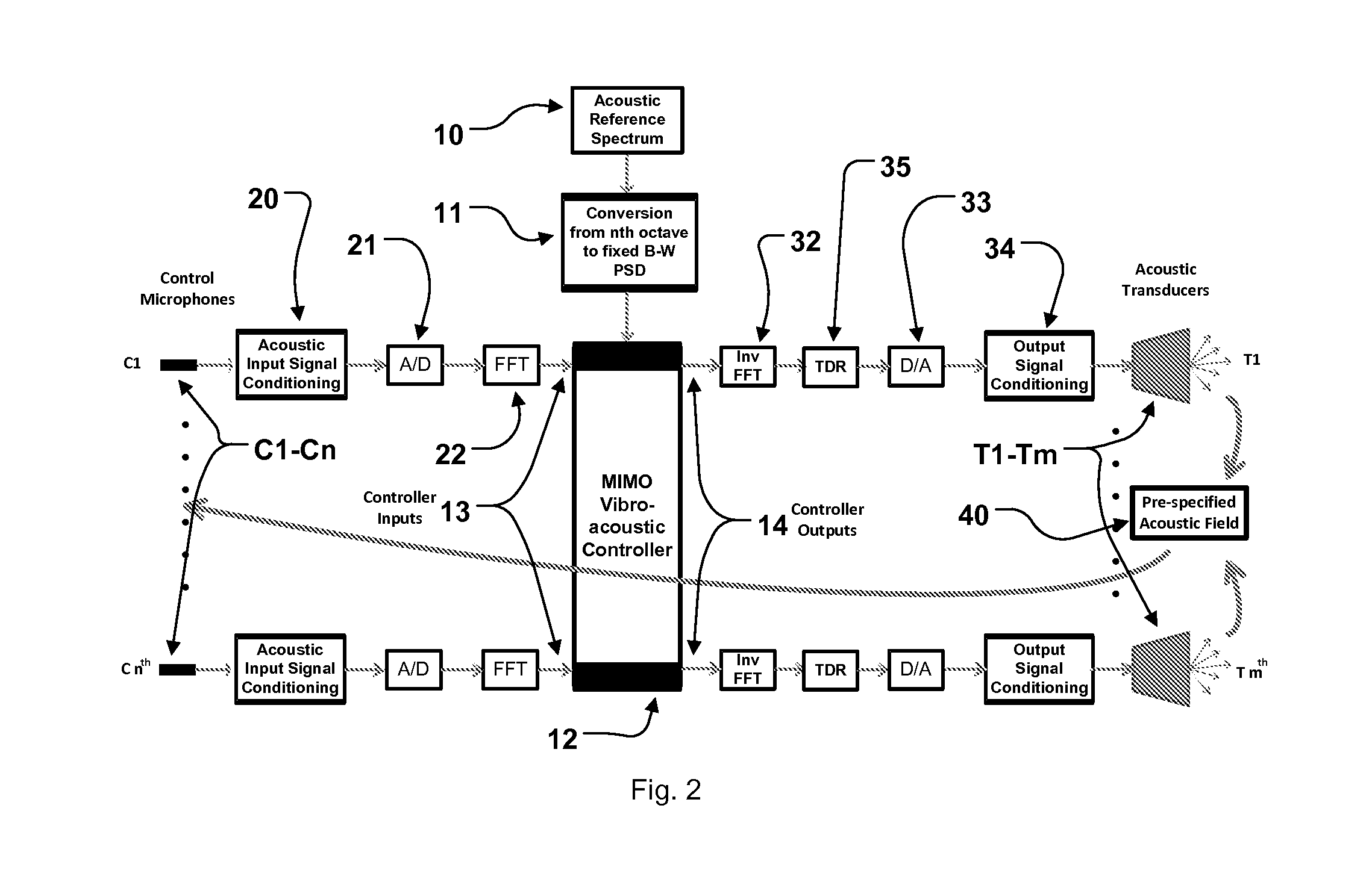
[0019]Referring to FIG. 1, an embodiment of a DFAT system in accordance with co-pending U.S. application Ser. No. 13 / 117,870, filed May 27, 2011 (“the '870 application) is shown. Included is a transducer array composed of electro-dynamic acoustic sources or transducers T1-T12 covering various frequency ranges arrayed around the unit-under test (UUT) 3 in a generally circular arrangement as shown. The transducer array in the embodiment shown is composed of twelve groups T1-T12 of eight transducers, of which nine groups ...


PUM

PropertyMeasurementUnit
internal volumeaaaaaaaaaa
frequencyaaaaaaaaaa

Abstract

An acoustic testing system includes at least four control microphones, at least four acoustic transducers, an acoustic enclosure with pre-determined reverberant characteristics which contains the at least four control microphones and the at least four acoustic transducers, a control system configured to produce a predetermined acoustic field as measured by the at least one control microphone. A unit under test is also disposed within the acoustic enclosure. Using an acoustic enclosure with pre-determined reverberant characteristics results of the increased proportion of reflected sounds in the area proximate to the unit under test such that less power is required to achieve a given acoustic test level than in a purely direct field acoustic test.

Description

CROSS-REFERENCE TO RELATED APPLICATION[0001]The present application claims priority under 35 U.S.C. §119(e) to U.S. provisional application no. 61 / 713,648 filed Oct. 15, 2012, the disclosure of which is incorporated by reference herein in its entirety.BACKGROUND OF THE INVENTION[0002]1. Field of the Invention[0003]The present invention relates generally to the field of vibration testing of objects such as satellites, instrumentation or any other object whose reliability in operation may be evaluated using high intensity vibration testing. Specifically, the present invention relates to the application of techniques developed for direct field acoustic testing systems to the performance of vibration testing to a predetermined specification in a semi-reverberant enclosure.[0004]2. Background of the Invention[0005]The specification of co-pending U.S. application Ser. No. 13 / 117,870, filed May 27, 2011 titled Direct Field Acoustic Testing System and Method (hereinafter “the '870 applicati...

Claims


Application Information

Patent Timeline
Patent Type & Authority Applications(United States)
IPC IPC(8): G01N29/30G01N29/04
CPCG01N29/30G01N29/04G01N2291/023G01N2291/105G01N2291/0289G01N29/11G01N29/46G01M7/00H04R3/12H04R5/02G01N2291/2698G01N29/226G01N29/223
Inventor LARKIN, PAULPOLK, MATTHEWHAYES, DANN
Owner MSI DFAT
Why Eureka
Try Eureka