System and Method for 3D SAR Imaging using Compressive Sensing with Multi-Platform, Multi-Baseline and Multi-PRF Data

Active Publication Date: 2015-09-10
MITSUBISHI ELECTRIC RES LAB INC
View PDF3 Cites 36 Cited by
  • Summary
  • Abstract
  • Description
  • Claims
  • Application Information

AI Technical Summary

Benefits of technology

[0010]The embodiments of the invention provide a compressive sensing sensing (CS) based method for synthetic aperture radar (SAR) imaging. The method reduces the total amount of raw data that need to be acquired, and increases a resolution of el

Problems solved by technology

In particular, using the CS-based method, 3D reflectivity can be generated using onl

Method used


Image

  • System and Method for 3D SAR Imaging using Compressive Sensing with Multi-Platform, Multi-Baseline and Multi-PRF Data
  • System and Method for 3D SAR Imaging using Compressive Sensing with Multi-Platform, Multi-Baseline and Multi-PRF Data
  • System and Method for 3D SAR Imaging using Compressive Sensing with Multi-Platform, Multi-Baseline and Multi-PRF Data

Examples


Embodiment Construction

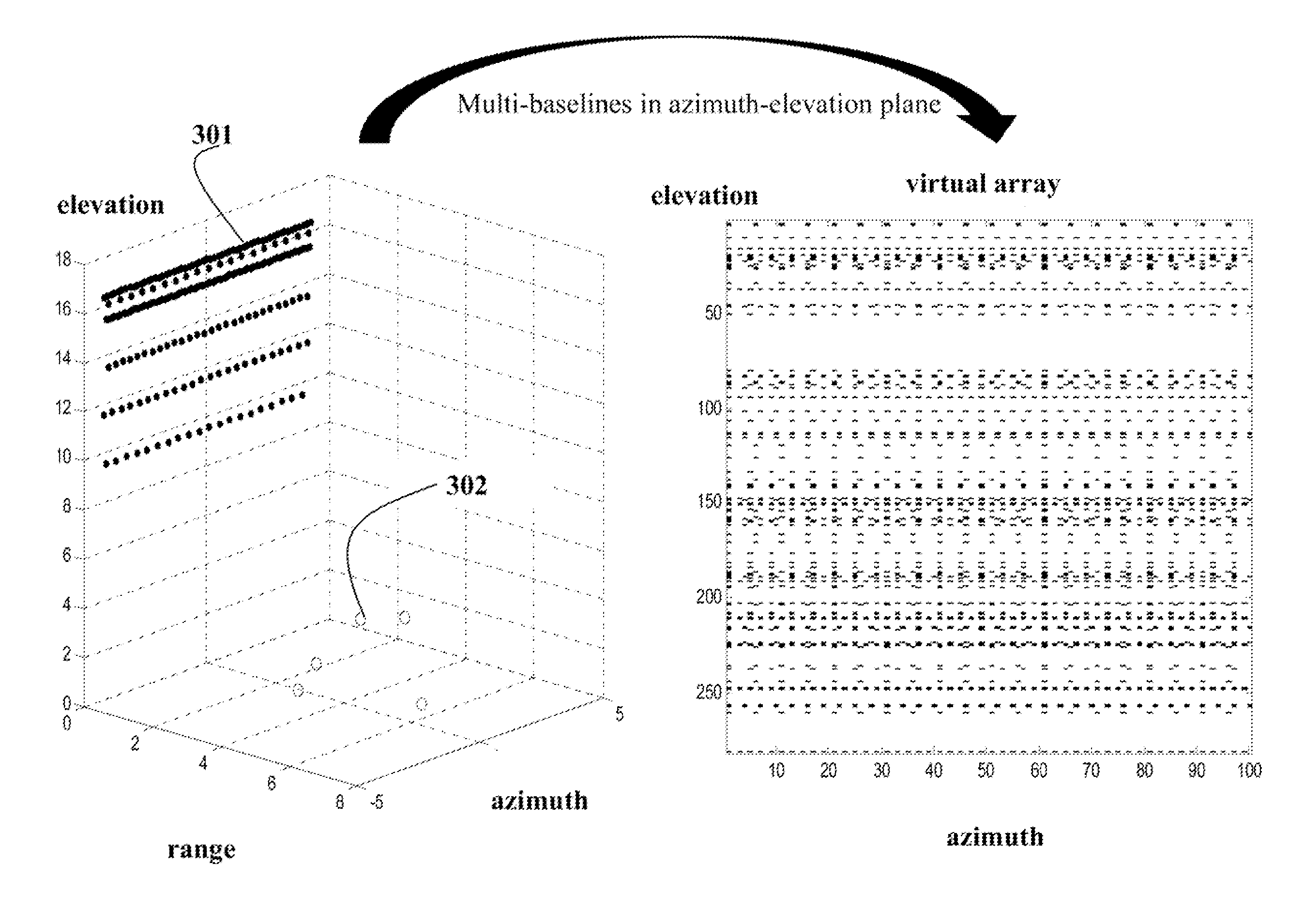
[0022]As shown in FIGS. 3 and 4, the embodiments of the invention provide a method lot generating a synthetic aperture radar (SAR) 3D image. The method acquires data sets at multiple baselines 301 and multiple pulse repetition frequency (PRF). The multiple base lines can be established using a single platform performing several passes over an area of interest, or multiple different platforms passing over the same area.

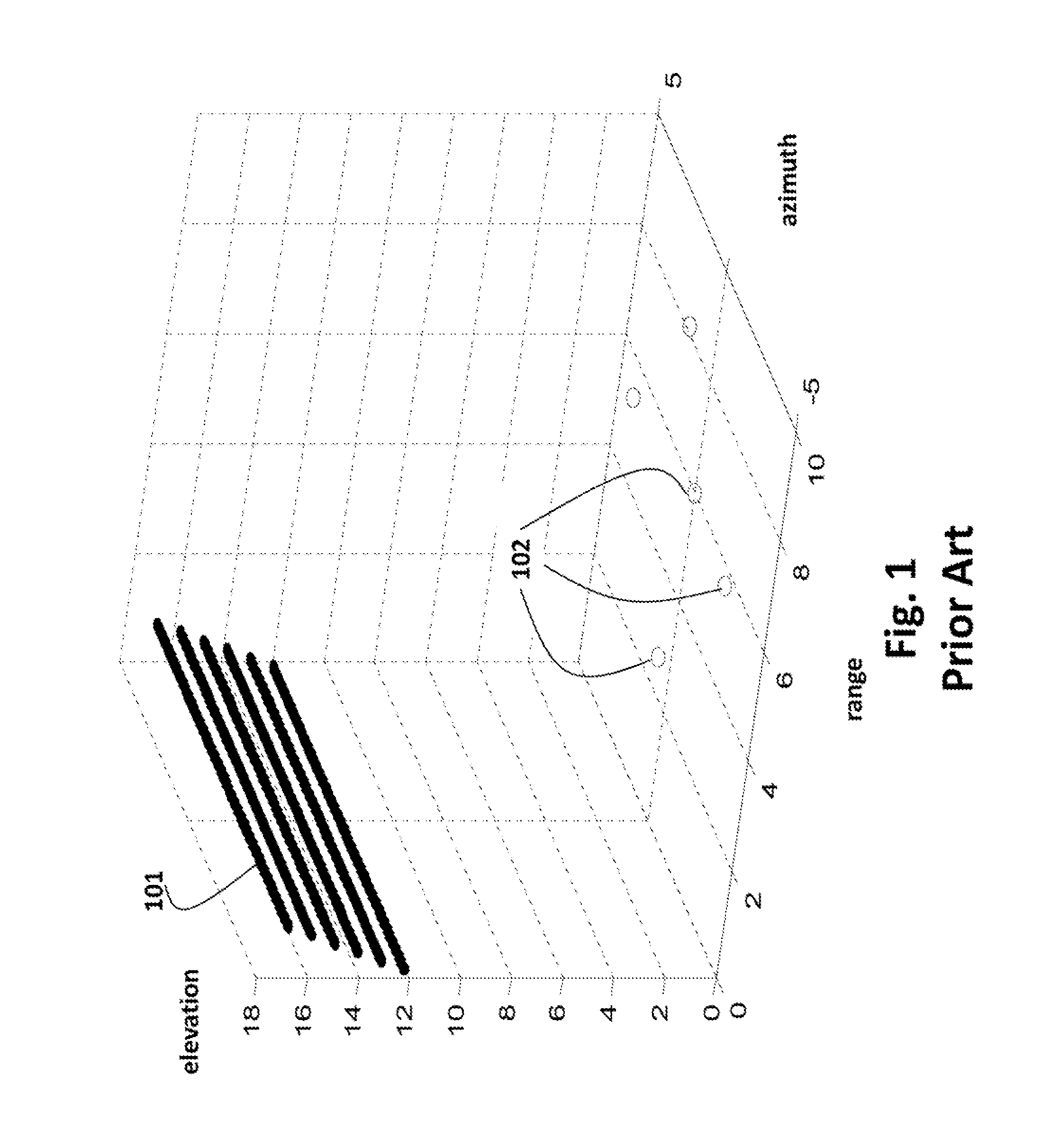
[0023]For the purpose of this description, we consider point scatterers 302 as well as 3D objects placed in a 3D space. We consider a total of 70 baselines randomly distributed in space along elevation direction. These baselines are selected from 281 possible baselines, uniformly spaced along the elevation, see FIG. 3. The total number of baselines is substantially less than for a conventional 3D SAR system.

[0024]In our simulation, we only need 25% of total baselines needed for a conventional 3D SAR system, yet we can increase the elevation resolution by about 4 times....


PUM


Abstract

A method generates a 3D synthetic aperture radar (SAR) image of an area by first acquiring multiple data sets from the area using one or more SAR systems, wherein each SAR system has one or more parallel baselines and multiple pulse repetition frequency (PRF), wherein the PRF for each baseline is different. The data sets are registered and aligned to produce aligned data sets. Then, a 3D compressive sensing reconstruction procedure is applied to the aligned data sets to generate the 3D image corresponding to the area.

Description

FIELD OF THE INVENTION[0001]This invention relates generally to synthetic radar systems, and more particularly to tomographic 3-dimensional imaging systems.BACKGROUND OF THE INVENTION[0002]Synthetic aperture radar (SAR) systems exploit the motion of antennas arranged on a moving platform to synthesize a large virtual aperture and, thus, achieve high resolution imaging. Each virtual array at different spatial location forms a baseline. A single pass (single baseline) SAR system is capable of imaging a 2-dimensional (2D) range-azimuth reflectivity of an area of interest without any elevation resolution. However, the 3-dimensional (3D) structure of the area, such as 3D terrain features, is not preserved.[0003]The 2D image is essentially a projection of the 3D reflectivity space into the 2D range-azimuth imaging plane. This projection can cause several artifacts. For example, in layover artifacts, several terrain patches with different elevation angles are mapped in the same range-azimu...

Claims


Application Information

Patent Timeline
IPC IPC(8): G01S13/90
CPCG01S13/9035G01S13/904G01S13/22G01S13/42H03M7/3062
Inventor LIU, DEHONGBOUFOUNOS, PETROS T.
Owner MITSUBISHI ELECTRIC RES LAB INC
Why Eureka
Try Eureka