Downhole Cable Termination Systems

a cable termination and cable technology, applied in cable terminations, borehole/well accessories, coupling device connections, etc., can solve problems such as the ttubing hanger, reduce the risk of sealing damage, and minimize the gap between the sleeve and the cable. , the effect of reducing the risk of local electrical stress

Inactive Publication Date: 2015-09-10
SIEMENS AG
View PDF1 Cites 6 Cited by
  • Summary
  • Abstract
  • Description
  • Claims
  • Application Information

AI Technical Summary

Benefits of technology

[0125]The join between the first part of the sleeve and the second part of the sleeve may be fixed by any known manner such as adhesive or mechanical fasters. Preferably, the second part of the sleeve is attached to the first part of the sleeve by being threadedly engaged therewith. By joining the second part of the sleeve to the first part of the sleeve by threaded engagement, the joining of the two parts may be achieved easily during manufacture. Additionally, joining the two parts by threaded engagement reduces the risk of damaging seals that are located near the join during the joining process.
[0126]In a preferred embodiment of the assembly, an end face at a downhole end portion of the second part of the sleeve is in contact with the protective sheath of the cable to which the first portion is attached. When the second part of the sleeve is arranged to abut the end of the protective sheath to which the first part of the sleeve is attached, gaps between the sleeve and the cable may be minimized. This may help prevent air being trapped around the cable that may cause electrical discharges if the electrical gradient around the cable is high enough. This also allows the earth profile provided by the protective sheath of the cable to be continued and to allow the earth to be ended with a smooth, rounded profile which minimizes local electrical stress.

Problems solved by technology

Such connectors in the tubing hanger are subjected to hostile conditions, such as extreme temperatures and pressures and aggressive chemicals, and thus the connectors are to be designed to deal with these conditions.

Method used


Image

  • Downhole Cable Termination Systems
  • Downhole Cable Termination Systems
  • Downhole Cable Termination Systems

Examples


Embodiment Construction

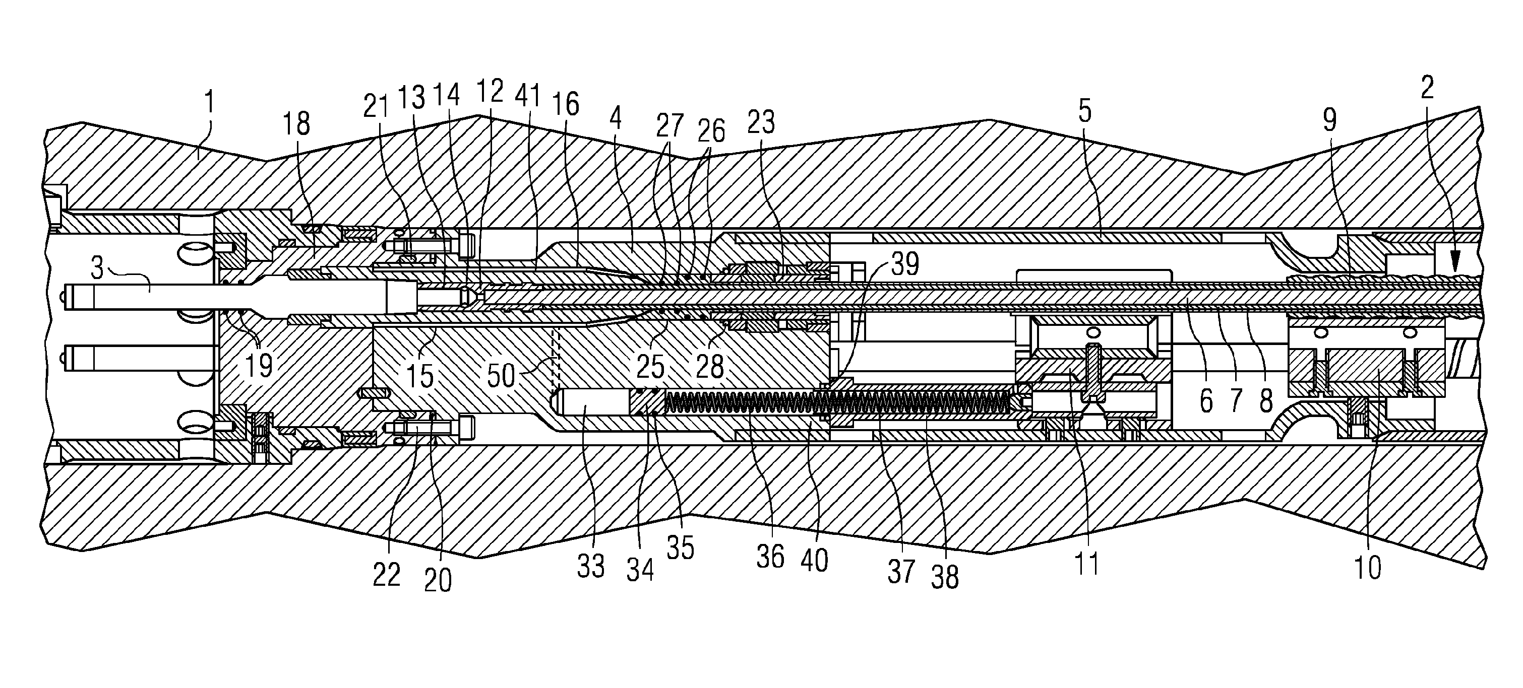
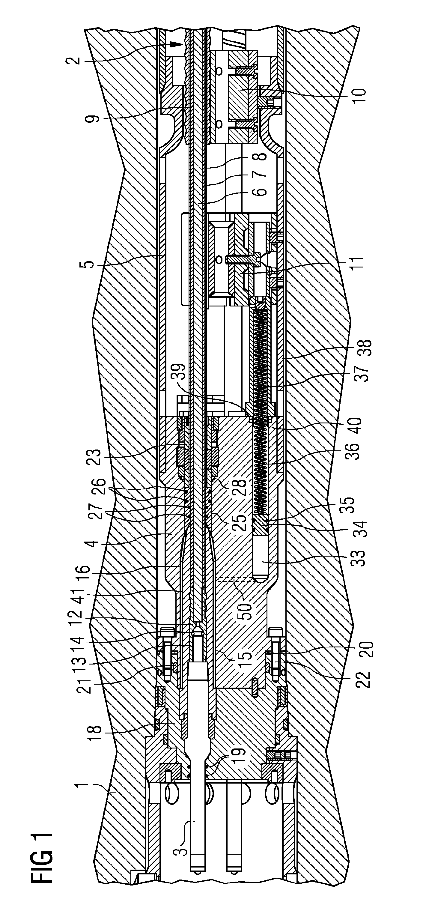
[0133]FIG. 1 shows a downhole cable termination assembly in a tubing hanger 1. A termination is made between a cable 2 and a pin 3 of a connector half that is arranged to be connected to another connector half to form a connector. The cable 2 extends downhole from the termination through a termination cover 4 and a tubing hanger receptacle gland housing 5 to electrical equipment (not shown) such as an electric submersible pump. Typically, there are three cables within the termination apparatus, each of which is terminated to a pin 3 of the connector half. The arrangement shown in FIG. 1 has three cables, although the cross section is only through one of the cables and the corresponding compensation chamber (discussed below).

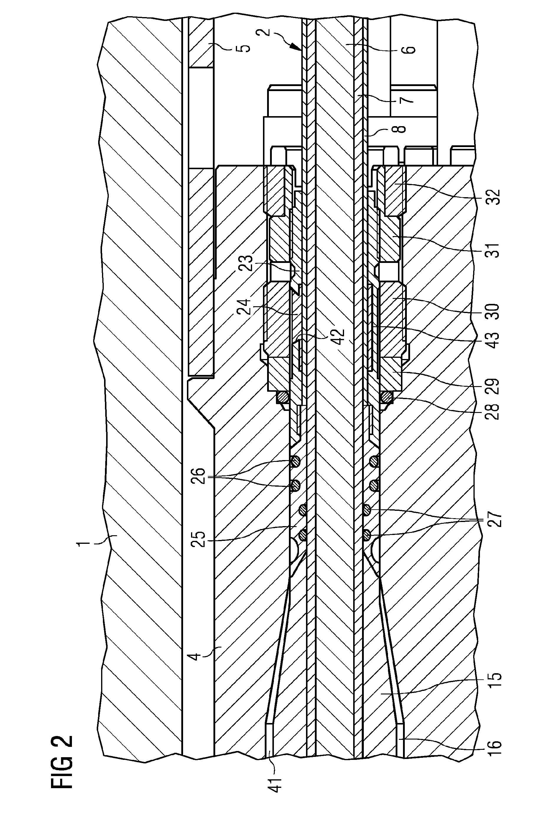
[0134]The cable 2 includes a conductive copper core 6 within an insulating polyether ether ketone (PEEK) sheath 7 that is within a lead sheath 8 and finally that is within a steel armour 9. Each layer of the cable 2 is concentric with the others. At a downhole po...


PUM

PropertyMeasurementUnit
temperatureaaaaaaaaaa
inner diameteraaaaaaaaaa
insulatingaaaaaaaaaa

Abstract

A downhole cable termination apparatus is provided for terminating a cable that is to extend downhole from a tubing hanger to electrical equipment. The apparatus includes: a first seal for sealing the apparatus uphole of the first seal from the downhole environment; a second seal for sealing the apparatus uphole of the second seal from the downhole environment; and a sleeve arranged to extend around the cable and to be attached to the cable, the sleeve being for providing a radially outwardly facing engagement portion for the first seal and a radially inwardly facing engagement portion for the second seal, the sleeve having two parts, a first part being arranged to be attached to the cable and providing the radially outwardly facing engagement portion, and a second part providing the radially inwardly facing engagement portion and provided separately from the first part, and the sleeve being arranged such that when the apparatus is assembled on the cable the second part is joined to the first part.

Description

RELATED CASES[0001]The present patent document is a §371 nationalization of PCT Application Serial Number PCT / EP2013 / 065984, filed Jul. 30, 2013, designating the United States, which is hereby incorporated by reference. This patent document also claims the benefit of GB 1217790.3, filed Oct. 4, 2012, and U.S. 61 / 709,498, filed Oct. 4, 2012, which are also hereby incorporated by reference.FIELD[0002]The present embodiments relate to a downhole cable termination apparatus and more specifically an apparatus for terminating a cable that is to extend downhole into a downhole environment from a tubing hanger to electrical equipment. The present embodiments also relate to downhole termination assemblies and methods of manufacturing downhole termination assemblies.BACKGROUND[0003]Typically a subsea well is provided with a tubing hanger for suspending production tubing that extends into a reservoir or a dummy reservoir. The tubing hanger may also house a connector that terminates a cable tha...

Claims


Application Information

Patent Timeline
Patent Type & Authority Applications(United States)
IPC IPC(8): H02G15/04H02G1/14
CPCH02G1/14H02G15/043E21B17/028H01R13/5202H01R13/5205H01R13/523H01R13/533H02G15/046E21B33/0385Y10T29/49174Y10T29/49179E21B17/023H01R13/521H01R13/5216E21B17/0285
Inventor BURROW, CHRISTOPHERSIMMONDS, MARK
Owner SIEMENS AG
Why Eureka
Try Eureka