Liquid viscosity detecting method for liquid droplet ejecting device, control method for liquid droplet ejecting device, and liquid droplet ejecting device

a liquid viscosity detection and liquid droplet technology, applied in printing, other printing apparatuses, etc., can solve the problems of inability to detect image density fluctuation, image partly absent, etc., to achieve accurate detection of a small change in ink viscosity

Active Publication Date: 2015-09-17
RICOH KK
View PDF1 Cites 26 Cited by
  • Summary
  • Abstract
  • Description
  • Claims
  • Application Information

AI Technical Summary

Benefits of technology

[0010]In view of the above circumstances, in one aspect, the present invention proposes a liquid viscosity detection method in the liquid droplet ejecting device including detecting amplitude values of a residual

Problems solved by technology

As the ink viscosities are changed among the nozzles, the ejecting speed of the respective nozzles vary, which may cause defective image formation such as image density fluctuation, image partly absent creating white lines, and color tone change.
When the ink viscosity is further increased, the nozzle is clogged, the image in which the ink is partly absent

Method used


Image

  • Liquid viscosity detecting method for liquid droplet ejecting device, control method for liquid droplet ejecting device, and liquid droplet ejecting device
  • Liquid viscosity detecting method for liquid droplet ejecting device, control method for liquid droplet ejecting device, and liquid droplet ejecting device
  • Liquid viscosity detecting method for liquid droplet ejecting device, control method for liquid droplet ejecting device, and liquid droplet ejecting device

Examples


Embodiment Construction

[0034]In the following, embodiments of the present invention will be described with reference to the accompanying drawings. It should be noted that configuration elements that include substantially the same functional configurations in the present specification and the drawings are assigned the same reference numerals and the duplicated description is omitted.

[0035]

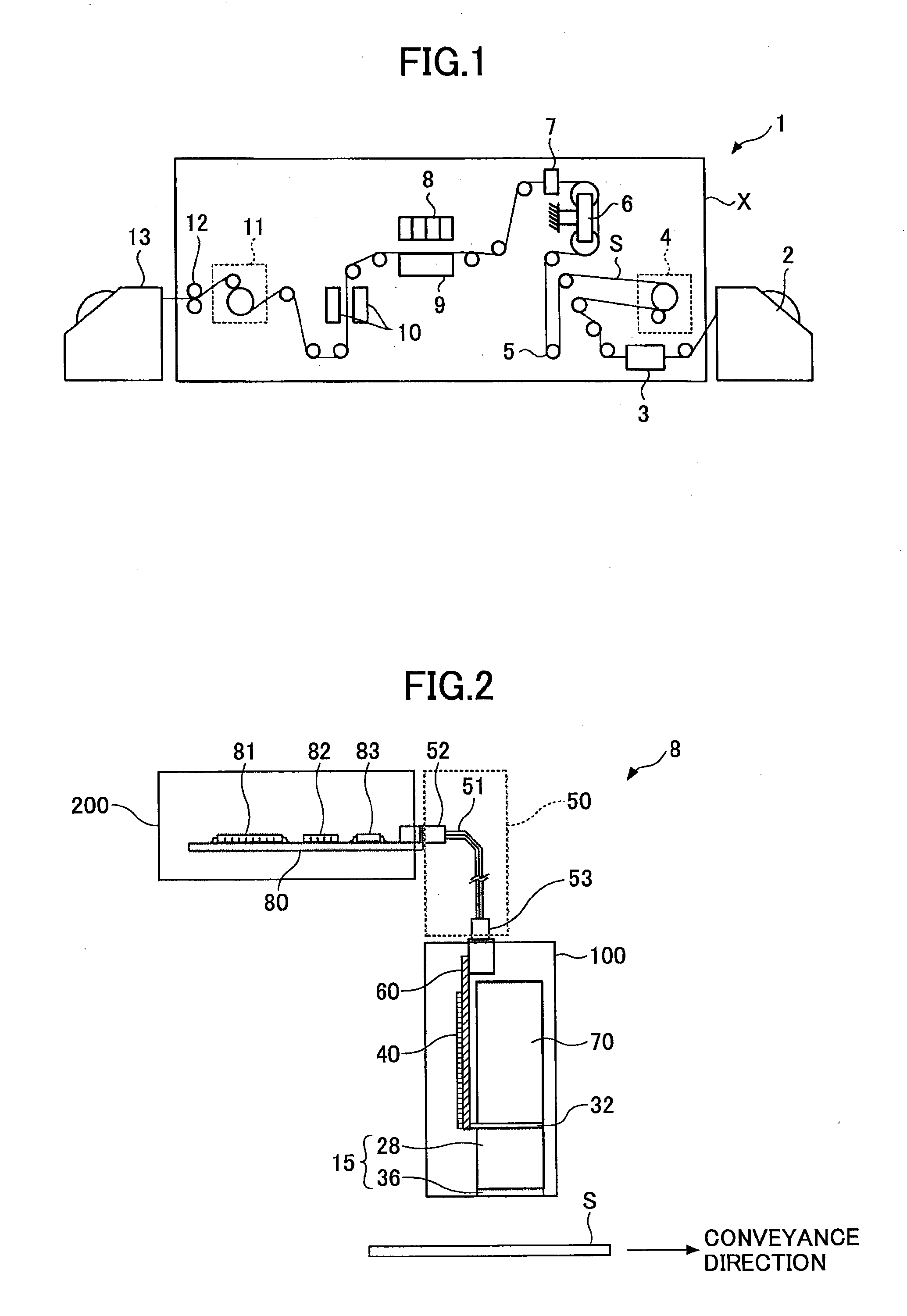
[0036]FIG. 1 is a schematic illustrating an entire configuration of an on-demand type line scanning inkjet recording apparatus 1. In FIG. 1, the inkjet recording apparatus 1 includes an inkjet ejecting apparatus body X, a recording medium supply unit 2, and a recording medium collection unit 13.

[0037]The inkjet apparatus body X includes a restriction guide 3, an in-feed unit 4, a dancer roller 5, an EPC 6, a conveyance meandering detector 7, an inkjet recording module 8, a platen 9, a drying module 10, an out-feed unit 11, and a puller 12.

[0038]The restriction guide 3 performs positioning of the recording medium S in a wi...


PUM


Abstract

A liquid viscosity detecting method is performed in a liquid droplet ejecting device that includes a piezoelectric type droplet ejecting head to which a drive waveform is applied to pressurize a liquid chamber to eject a liquid droplet, a drive waveform generator to apply the drive waveform to the droplet ejecting head, and a residual vibration detector. The method includes detecting, by the residual vibration detector, amplitude values of multiple cycles of a residual vibration waveform occurring within the liquid chamber after the drive waveform is applied; calculating an attenuation ratio based on the amplitude values; and calculating a liquid viscosity in the liquid chamber based on the attenuation ratio.

Description

BACKGROUND OF THE INVENTION[0001]1. Field of the Invention[0002]The present invention relates to a liquid viscosity detecting method for a liquid droplet ejecting device, a control method for a liquid droplet ejecting device, and a liquid droplet ejecting device.[0003]2. Description of the Related Art[0004]Inkjet recording apparatuses using, for example liquid droplet ejecting devices, have been known as image forming apparatuses such as printers, facsimile machines, copiers, multifunction peripherals (MFP), etc. In the inkjet recording apparatuses, inkjet recording heads are adapted to eject ink droplet onto recording media, such as papers or viewgraphs (OHP sheet) to form a desired image. As the inkjet recording head, there is known a piezoelectric type head in which a piezoelectric element is used as a pressure generator element to pressurize the ink in an ink channel to cause a vibration plate that forms a wall of the ink channel to vibrate, which changes a volume of the ink cha...

Claims


Application Information

Patent Timeline
IPC IPC(8): B41J2/045
CPCB41J2/04581B41J2/04588B41J2/04571B41J2/14233B41J2002/14354
Inventor HAYASHI, RYUICHI
Owner RICOH KK
Why Eureka
Try Eureka