Thermal management system for vehicle

a technology of management system and vehicle, applied in the direction of electric devices, battery/fuel cell control arrangement, lighting and heating apparatus, etc., can solve the problems of not being able to arbitrarily switch and circulate a heat medium in a different temperature zone according to a temperature adjustment target device, and being difficult to adjust the temperature adjustment target device to an appropriate temperatur

Active Publication Date: 2015-09-17
DENSO CORP
View PDF13 Cites 56 Cited by
  • Summary
  • Abstract
  • Description
  • Claims
  • Application Information

AI Technical Summary

Benefits of technology

[0020]Further, the reserve tank is connected to only one flow path of the numerous flow paths via the circulation flow path, and thereby it can suppress the reserve tank from forming a local loop circuit.

Problems solved by technology

As a result of studies by the inventors of the present application, if there is a difference in pump output between the respective coolant loops in the first mode of operating the two coolant loops in parallel, a leak of the coolant may occur inside the valve.
Thus, a local loop circuit is formed between the reserve tank and the valve, which might waste the power from a pump or compressor.
Further, the above thermal management system in the related art just switches the two coolant loops between the series connection and parallel connection, and thus cannot arbitrarily switch and circulate a heat medium in a different temperature zone according to a temperature adjustment target device.
As a result, it is difficult to adjust the temperature adjustment target device to an appropriate temperature depending on the situation.

Method used


Image

  • Thermal management system for vehicle
  • Thermal management system for vehicle
  • Thermal management system for vehicle

Examples


first embodiment

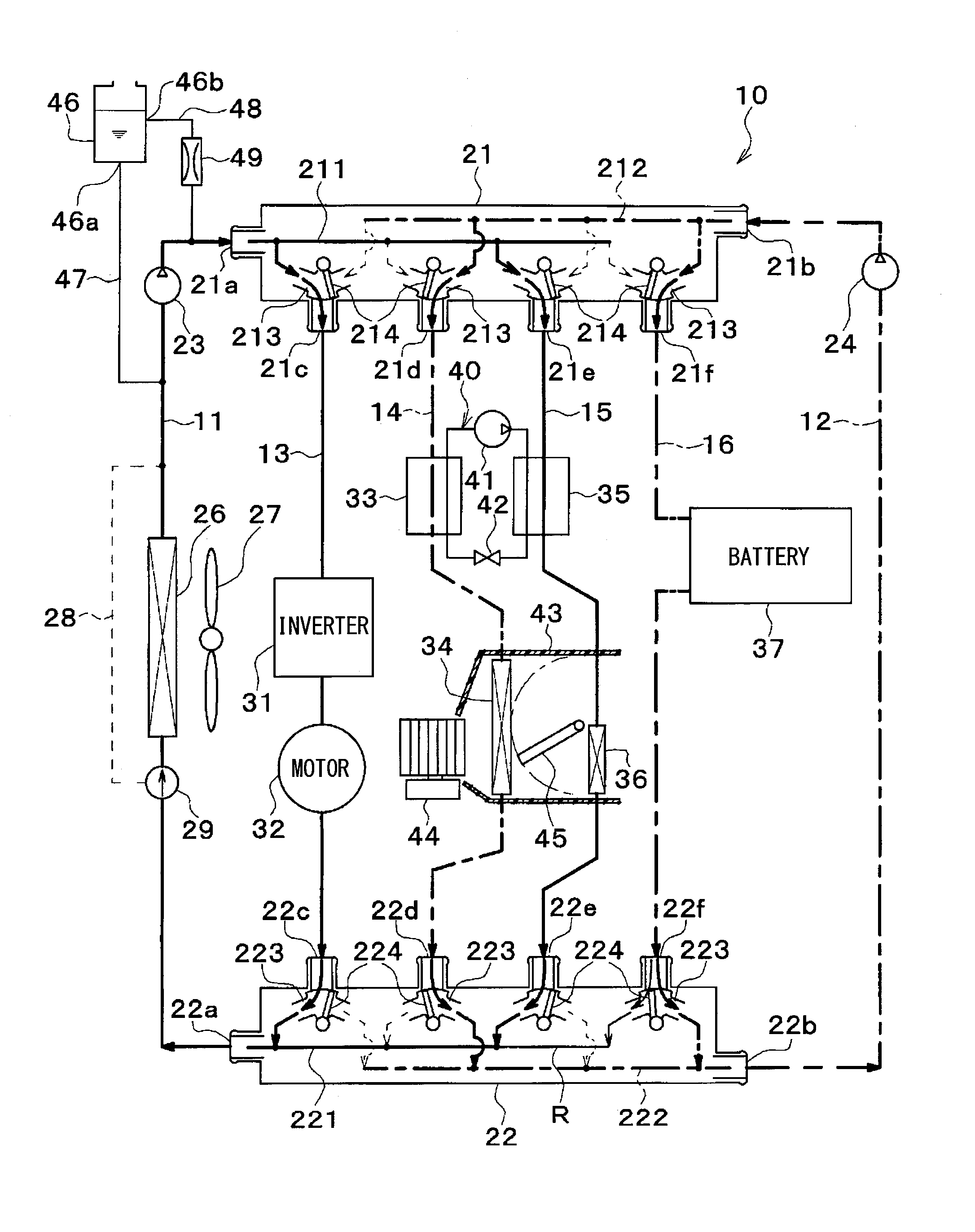
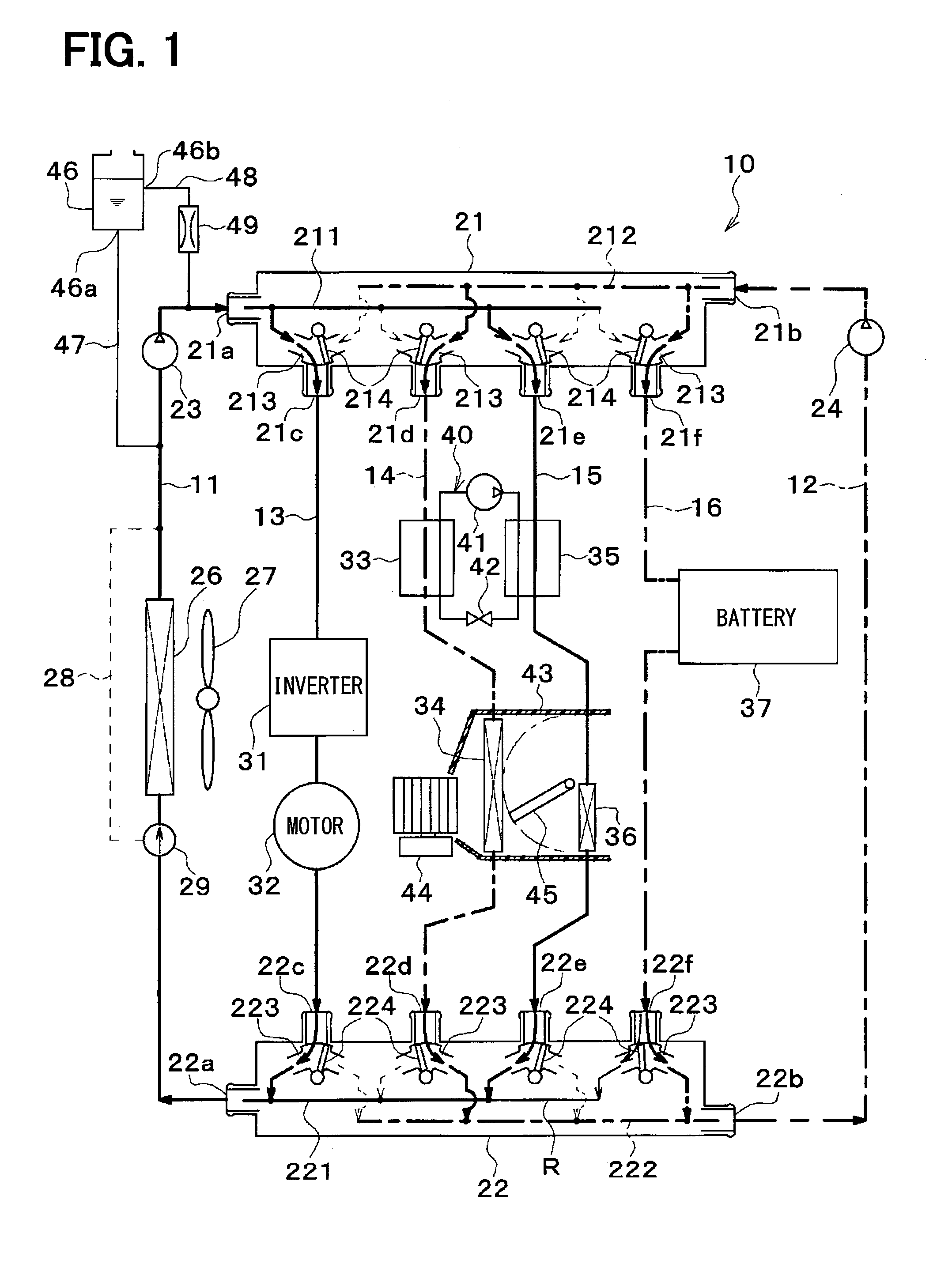
[0050]Now, a first embodiment of the invention will be described. A thermal management system 10 for a vehicle shown in FIG. 1 is used to cool various temperature adjustment target device included in a vehicle (devices requiring cooling or heating) to an appropriate temperature.

[0051]In the first embodiment, the thermal management system 10 is applied to a hybrid vehicle that can obtain the driving force for traveling from both an engine (internal combustion engine) and a motor for traveling.

[0052]The hybrid vehicle can switch between a traveling state (HV traveling) in which a vehicle can travel by obtaining a driving force from both the engine and electric motor for traveling by causing the engine to operate or stop according to a traveling load on the vehicle and a remaining storage energy of a battery or the like, and another traveling state (EV traveling) in which the vehicle can travel by obtaining a driving force only from the electric motor for traveling by stopping the engi...

second embodiment

[0143]Although in the first embodiment, the air-release reserve tank 46 is connected only to the first flow path 11, in a second embodiment of the invention, as shown in FIG. 3, the air-release reserve tank 46 is connected not only to the first flow path 11, but also to the second flow path 12.

[0144]The connection between the reserve tank 46 and the second flow path 12 is performed via the main connection flow path 47. The main connection flow path 47 is branched into two parts on the side opposite to the reserve tank 46, and the parts are connected to the first and second flow paths 11 and 12, respectively. The two parts 47a and 47b branched from the main connection flow path 47 are respectively provided with negative pressure valves 60. The sub-connection flow path 48 is provided with a pressurizing valve 61.

[0145]The negative pressure valve 60 operates to close when the internal pressure of the flow path is equal to or higher than atmospheric pressure, and to open when the intern...

third embodiment

[0161]Although in the second embodiment, the sub-connection flow path 48 is connected only to the first flow path 11, in a third embodiment of the invention, as shown in FIG. 4, the sub-connection flow path 48 is connected not only to the first flow path 11, but also to the second flow path 12.

[0162]The sub-connection flow path 48 is branched into two parts on the side opposite to the reserve tank 46, and the parts are connected to the first and second flow paths 11 and 12, respectively. The two branched parts 48a and 48b of the sub-connection flow path 48 are respectively provided with the pressurizing valves 61.

[0163]The end of the main connection flow path 47 opposite to the reserve tank 46 is connected to the part on the suction side of the first pump 23 in the first flow path 11 as well as the part on the suction side of the second pump 24 in the second flow path 12.

[0164]The end of the sub-connection flow path 48 opposite to the reserve tank 46 is connected to the part of the ...


PUM


Abstract

A thermal management system for a vehicle includes a first pump and a second pump, temperature adjustment target devices, heat exchangers, numerous flow paths including a first pump arrangement flow path, a second pump arrangement flow path, and device arrangement flow paths, a first switching portion for allowing the numerous flow paths to selectively communicate with each other, a second switching portion for allowing the numerous flow paths to selectively communicate with each other, and a reserve tank for storing therein heat medium. The reserve tank is configured to set the pressure of the liquid surface of the stored heat medium to a predetermined pressure (e.g., atmospheric pressure), and is connected to one flow path of the numerous flow paths.

Description

[0001]The application is based on Japanese Patent Applications No. 2012-187153 filed on Aug. 28, 2012, and No. 2013-139568 filed on Jul. 3, 2013, the contents of which are incorporated herein by reference in its entirety.FIELD OF THE INVENTION[0002]The preset disclosure relates to a thermal management system used for a vehicle.BACKGROUND ART[0003]Conventionally, as disclosed in Patent Document 1, a thermal management system includes a first coolant loop for exchanging heat with a battery system, a second coolant loop for exchanging heat with at least one drive train component, and a valve for switching between a first mode of operating the two coolant loops in parallel and a second mode of operating the two coolant loops in series.[0004]In the related art, the first coolant loop includes a first coolant reservoir, and the second coolant loop includes a second coolant reservoir. The first reservoir and the second reservoir are integrated together into a single dual-loop reservoir.[00...

Claims


Application Information

Patent Timeline
Patent Type & Authority Applications(United States)
IPC IPC(8): B60H1/32B60H1/00
CPCB60H1/00485B60H1/32B60L1/003B60L1/02B60L3/0092B60H1/00878B60L3/00B60H1/08B60L2240/34B60L2240/36B60L2240/425B60L2240/525B60L2240/545B60L2240/662Y02T90/16B60K11/02B60K2001/003B60K2001/005B60K2001/006B60L58/26B60L58/24Y02T10/64Y02T10/70Y02T10/72
Inventor ENOMOTO, NORIHIKOKAKEHASHI, NOBUHARUNISHIKAWA, MICHIOMAKIHARA, MASAMICHIKUWAYAMA, KAZUTOSHIKATOH, YOSHIKISUGIMURA, KENGO
Owner DENSO CORP
Why Eureka
Try Eureka