Laser scanning display device

Active Publication Date: 2015-09-17
NIPPON SEIKI CO LTD
View PDF6 Cites 35 Cited by
  • Summary
  • Abstract
  • Description
  • Claims
  • Application Information

AI Technical Summary

Benefits of technology

[0017]According to an embodiment of the invention, there is provided a laser scanning display device, which can quickly provide an image of stable disp

Problems solved by technology

Thus, even if a predetermined current is supplied to a laser source to obtain a desired light intensity, t

Method used


Image

  • Laser scanning display device
  • Laser scanning display device
  • Laser scanning display device

Examples


Embodiment Construction

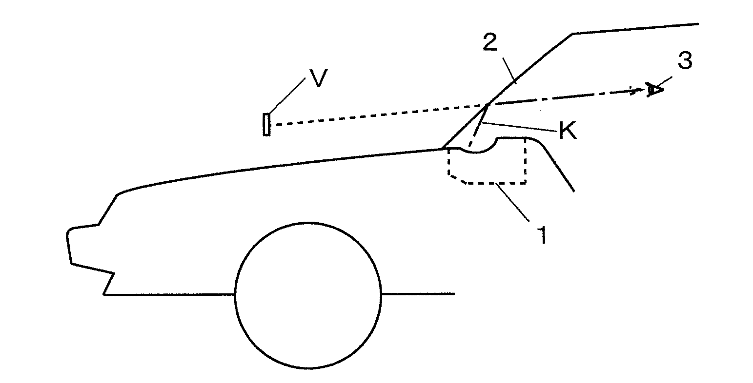
[0032]Hereinafter, based on the accompanying drawings, a description will be given of an embodiment wherein a laser scanning display device of the invention applies to a head-up display device (HUD device) to be mounted on a vehicle.

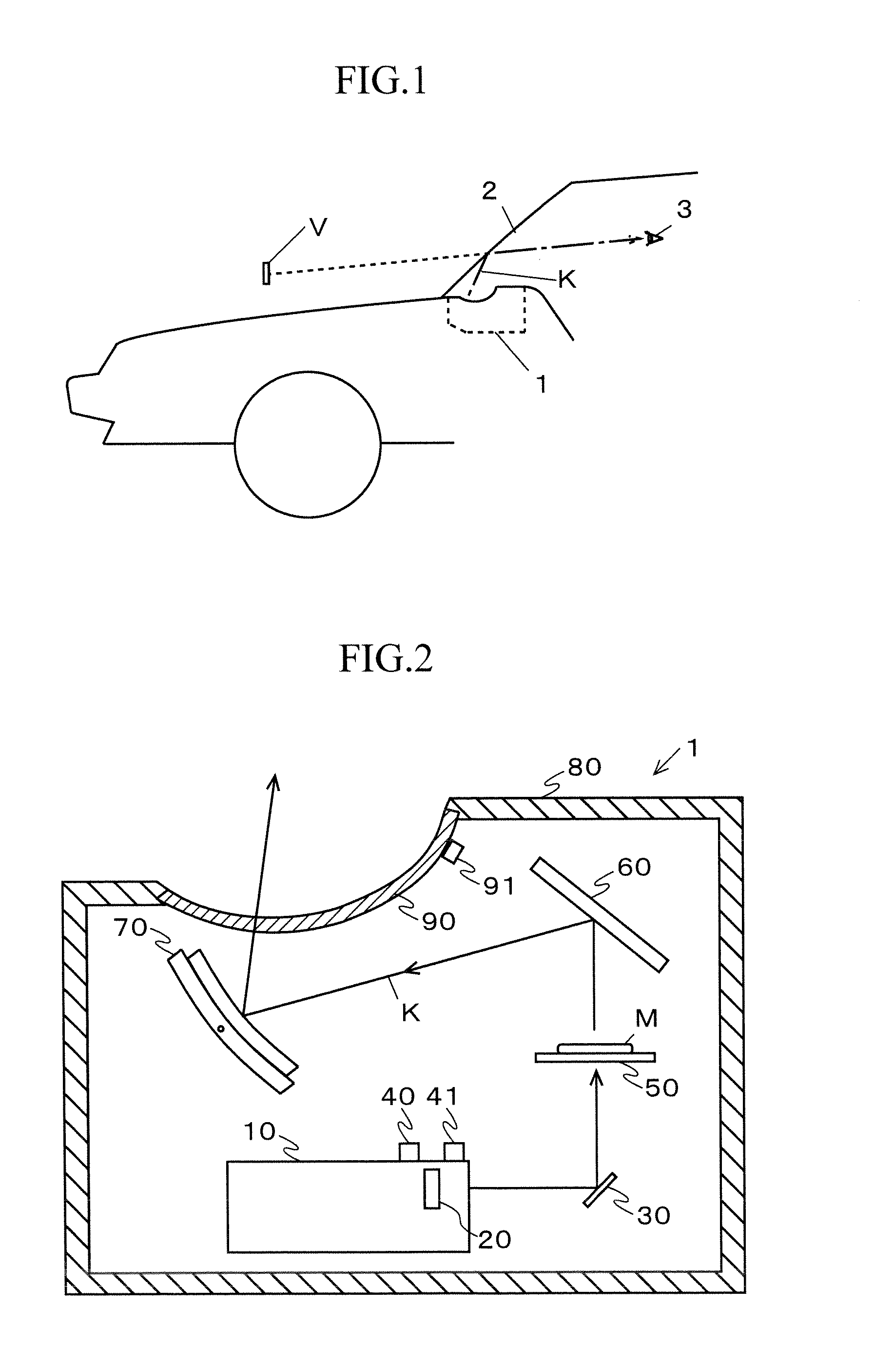
[0033]A HUD device 1 according to a first embodiment of the invention is disposed on a dashboard of a vehicle 2 as shown in FIG. 1, and configured to emit a display light K representing an image M (see FIG. 2) notifying predetermined information toward a windshield 3. The display light K is reflected by the windshield 3, and recognized by an observer (a driver of the vehicle 2 in most cases) as a virtual image V formed in front of the windshield 3. In this manner, the HUD device 1 causes the observer 3 to visually recognize the image.

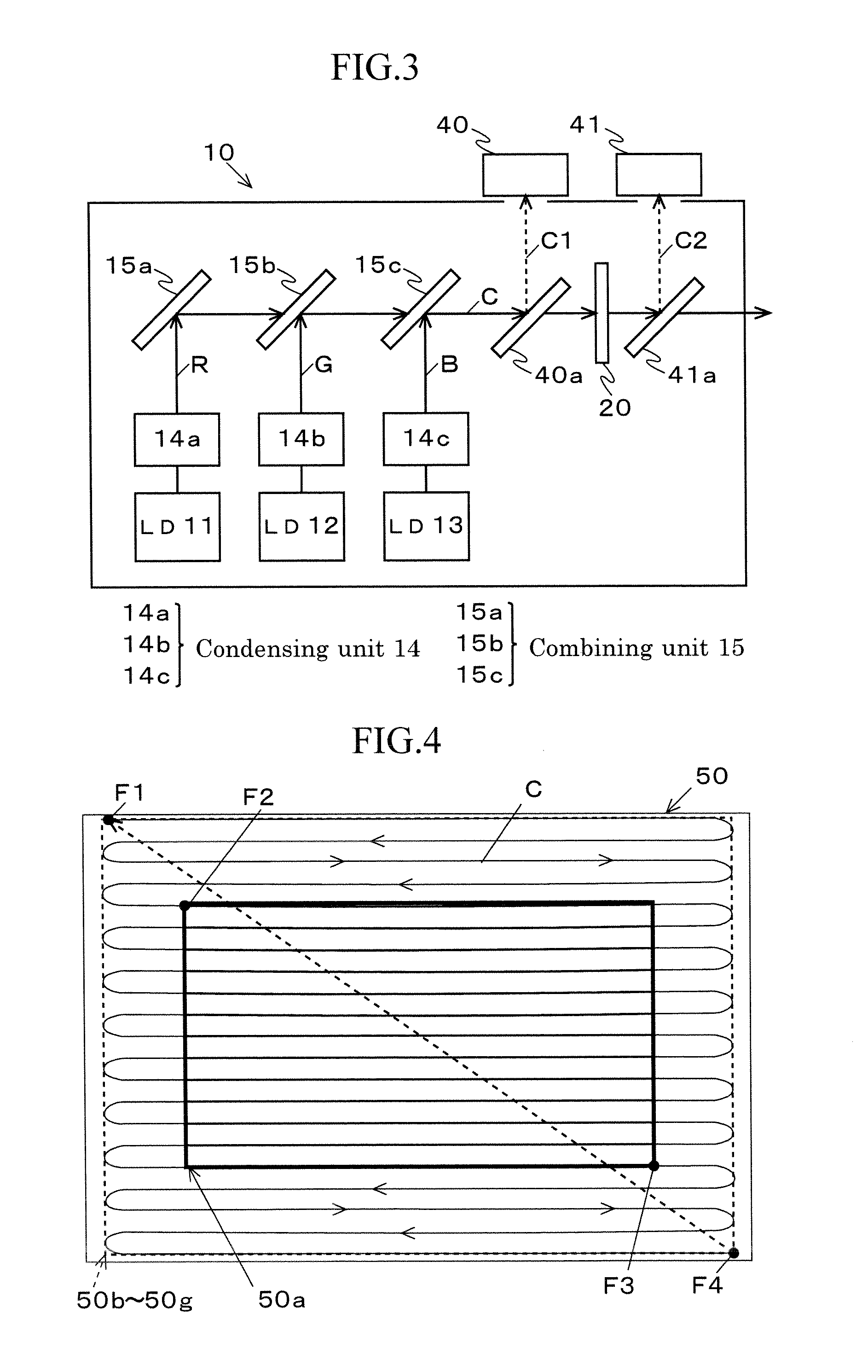
[0034]As shown in FIG. 2, the HUD device 1 comprises a composite laser light emission unit 10, a dimmer unit (dimmer means) 20, a micro electro mechanical system (MEMS) mirror (scanning means) 30, a first light detection uni...


PUM


Abstract

In order to enable a display image with stable display colors and display brightness to be obtained quickly even when the optical intensity characteristic of a laser light source changes due to a harsh usage environment, a Dimmer unit is equipped with: a first light detection unit that modulates the light intensity of composite laser light emitted from a composite laser light emission unit, and detects the light intensity of the composite laser light before entering the Dimmer unit; and a second light detection unit that detects the light intensity of the composite laser light after entering the Dimmer unit. The light intensity characteristic for each color in the composite laser light emission unit is calculated on the basis of the light intensity detected by the first light detection unit, and the white balance of each color in the composite laser light emission unit is adjusted on the basis of the light intensity detected by the second light detection unit.

Description

TECHNICAL FIELD[0001]The present invention relates to a laser scanning display device, which displays an image by optically scanning a laser light emitted from a laser light source.BACKGROUND ART[0002]Patent Literature 1 discloses a laser scanning display device, which generates a display image by scanning a laser light emitted from a laser light source on a screen through a scanning system.[0003]The current-light intensity characteristics of a laser light source (light intensity characteristics: the relationship between the supplied current and the emitted light intensity) change due to a driving heat, an outside temperature change and the like. Thus, even if a predetermined current is supplied to a laser source to obtain a desired light intensity, the desired light intensity is not obtained, and an image is not displayed with desired display brightness.[0004]Patent Literature 2 discloses a laser scanning display device, which supplies a current to a light source by changing a valu...

Claims


Application Information

Patent Timeline
IPC IPC(8): G02B26/02H04N9/31G02B26/10G02B27/01B60K35/00
CPCG02B26/02G02B27/0101B60K35/00G02B26/10G02B2027/014H04N9/3182G02B2027/0112G02B2027/0118H04N9/3129B60K2370/1529G02B27/01H04N9/3135H04N9/3155
Inventor YAMAKAWA, YASUHIROSEKIYA, SHUN
Owner NIPPON SEIKI CO LTD
Why Eureka
Try Eureka