
Method of driving LED chip

Inactive Publication Date: 2015-09-17
ESPEN TECH INC +1
View PDF4 Cites 4 Cited by
  • Summary
  • Abstract
  • Description
  • Claims
  • Application Information

AI Technical Summary

Benefits of technology

The patent describes a method to effectively control the brightness of LED chips by providing different levels of electrical energy based on the strength of the reference voltage. This solves the issue that conventional driving apparatus can only work with LED chips of the same specification. The technical effect is an improvement in the flexibility and efficiency of LED driving.

Problems solved by technology

If a manufacturer has to produce several types of driving apparatuses in order to drive LED chips with different specifications, the quantities of each type of driving apparatuses is limited.
Therefore, the price and the manufacturing cost are unlikely to be lowered, and that's why LED lighting appliances are more expensive than conventional kinds, which hinders such appliances from being further accepted by customers.

Method used


Image

  • Method of driving LED chip
  • Method of driving LED chip
  • Method of driving LED chip

Examples


Embodiment Construction

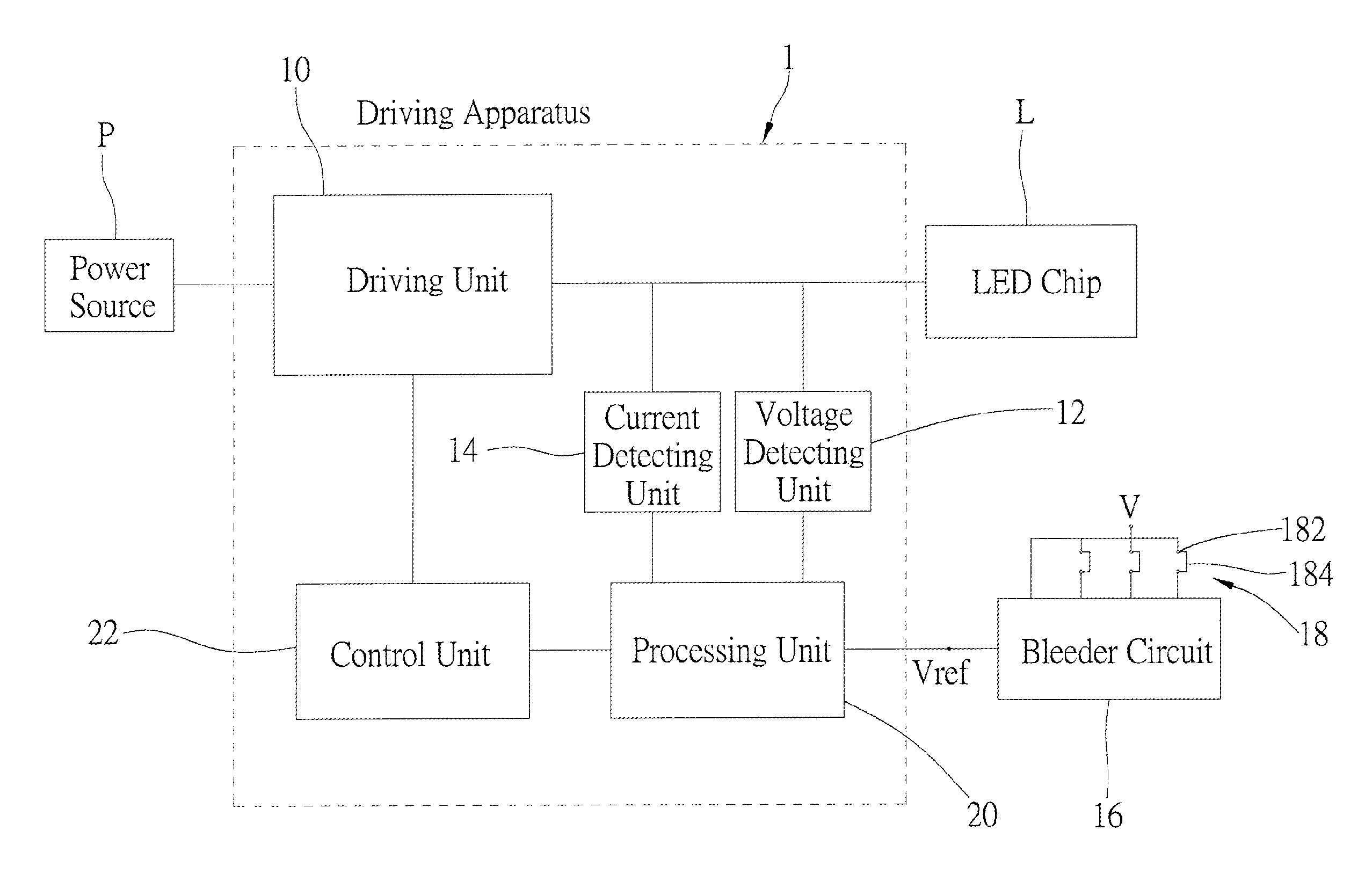
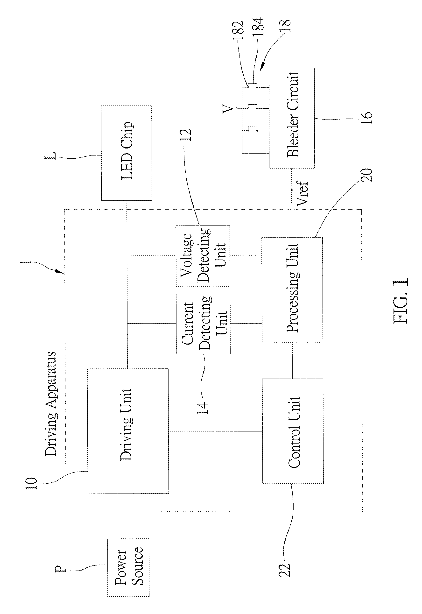
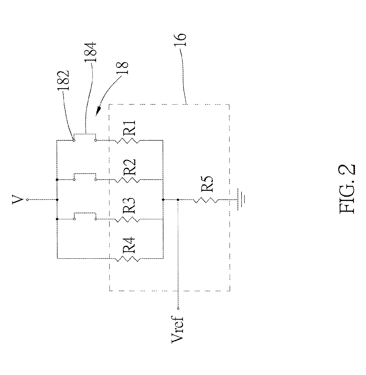
[0014]As shown in FIG. 1, a driving apparatus 1 suitable for applying the first preferred embodiment of the present invention includes a driving unit 10, a voltage detecting unit 12, a current detecting unit 14, a bleeder circuit 16, a plurality of switches 18, a processing unit 20, and a control unit 22.

[0015]The driving unit 10 is electrically connected to a power source P and a LED chip L. The driving unit 10 converts electrical energy provided by the power source P into an operating voltage and an operating current which are required by the LED chip L, and outputs the operating voltage and the operating current. The driving unit 10 can be controlled to provide electrical energy at one of a plurality of different powers. Furthermore, while providing electrical energy at one of the powers, the driving unit 10 is also controllable to change the operating current and the operating voltage. In practice, the driving unit 10 can be designed based on PWM, half-bridge, buck, or boost cir...


PUM


Abstract

A method of driving a LED chip includes the following steps: generate a reference voltage, and accordingly control a driving unit to output electrical energy at a power corresponding to the strength of the reference voltage; obtain an operating current required by the LED chip; control the driving unit to output the operating current to the LED chip under the power corresponding to the reference voltage. Whereby, with different strengths of the reference voltage, the driving unit is capable of outputting electrical energy to the LED chip at different powers. Therefore, one single driving apparatus applied with the method is sufficient to replace multiple conventional driving apparatuses for LED chips.

Description

BACKGROUND OF THE INVENTION[0001]1. Technical Field[0002]The present invention relates generally to driving a LED chip, and more particularly to a method of driving a led chip.[0003]2. Description of Related Art[0004]Typically, a LED (light-emitting diode) device includes a LED chip and a driving apparatus, wherein the driving apparatus provides electrical energy to the LED chip. There are various types of LED chips in the current market, and LED chips with different specifications may require different rated voltages and rated currents, even for those compatible with the same power. For example, a LED chip compatible with 28 W may have the following combinations of rated voltages and rated currents: 80V / 350 mA, 56V / 500 mA, 40V / 700 mA, etc. Not to mention those LED chips compatible with different powers, for apparently there must be a lot more combinations of rated voltages and rated currents.[0005]Conventionally, one specific type of driving apparatus can only drive LED chips with ...

Claims


Application Information

Patent Timeline
IPC IPC(8): H05B33/08H05B44/00
CPCH05B33/0815H05B33/0851H05B45/10H05B45/3725H05B45/385
Inventor LIN, MING-FENG
Owner ESPEN TECH INC
Learn More