
Discharge lamp driving device, light source device, projector, and discharge lamp driving method

Inactive Publication Date: 2015-09-17
SEIKO EPSON CORP
View PDF4 Cites 1 Cited by
  • Summary
  • Abstract
  • Description
  • Claims
  • Application Information

AI Technical Summary

Benefits of technology

This patent text describes a configuration for a projector that includes a heated electrode to prevent the tip of the electrode from melting during the mixing process. This configuration also includes a light source device that improves the reliability of the projector. The technical effect of this invention is to prevent extreme melting of the electrode tip and improve the reliability of the projector.

Problems solved by technology

However, in the driving method described above, the growth of a projection on the tip of the electrode is unlikely to be appropriately controlled in some cases due to the reason that the fluctuation in temperature may not be made to be sufficiently large.

Method used


Image

  • Discharge lamp driving device, light source device, projector, and discharge lamp driving method
  • Discharge lamp driving device, light source device, projector, and discharge lamp driving method
  • Discharge lamp driving device, light source device, projector, and discharge lamp driving method

Examples


Embodiment Construction

[0040]Hereinafter, a projector according to an embodiment of the invention will be described with reference to the accompanying drawings.

[0041]Further, the range of the invention is not limited to the embodiments described below and can be arbitrarily changed within the range of the technical scope of the invention. In addition, for the sake of easy description of each configuration, in the drawings below, the scales or the numerical values of each structure may be different from those of the actual structure.

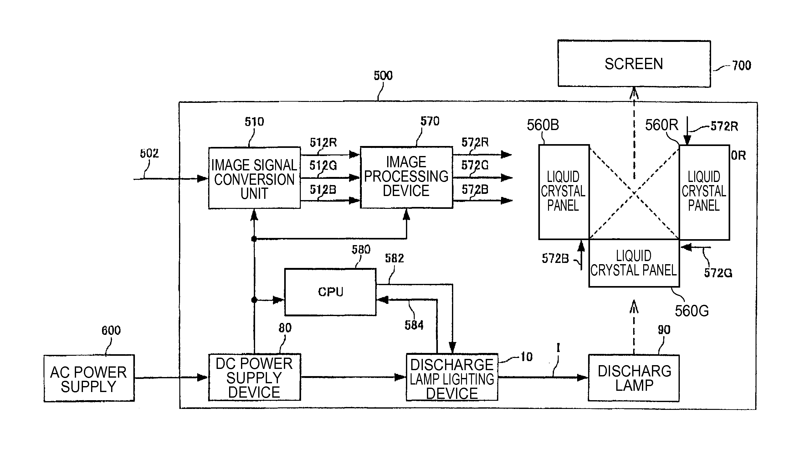
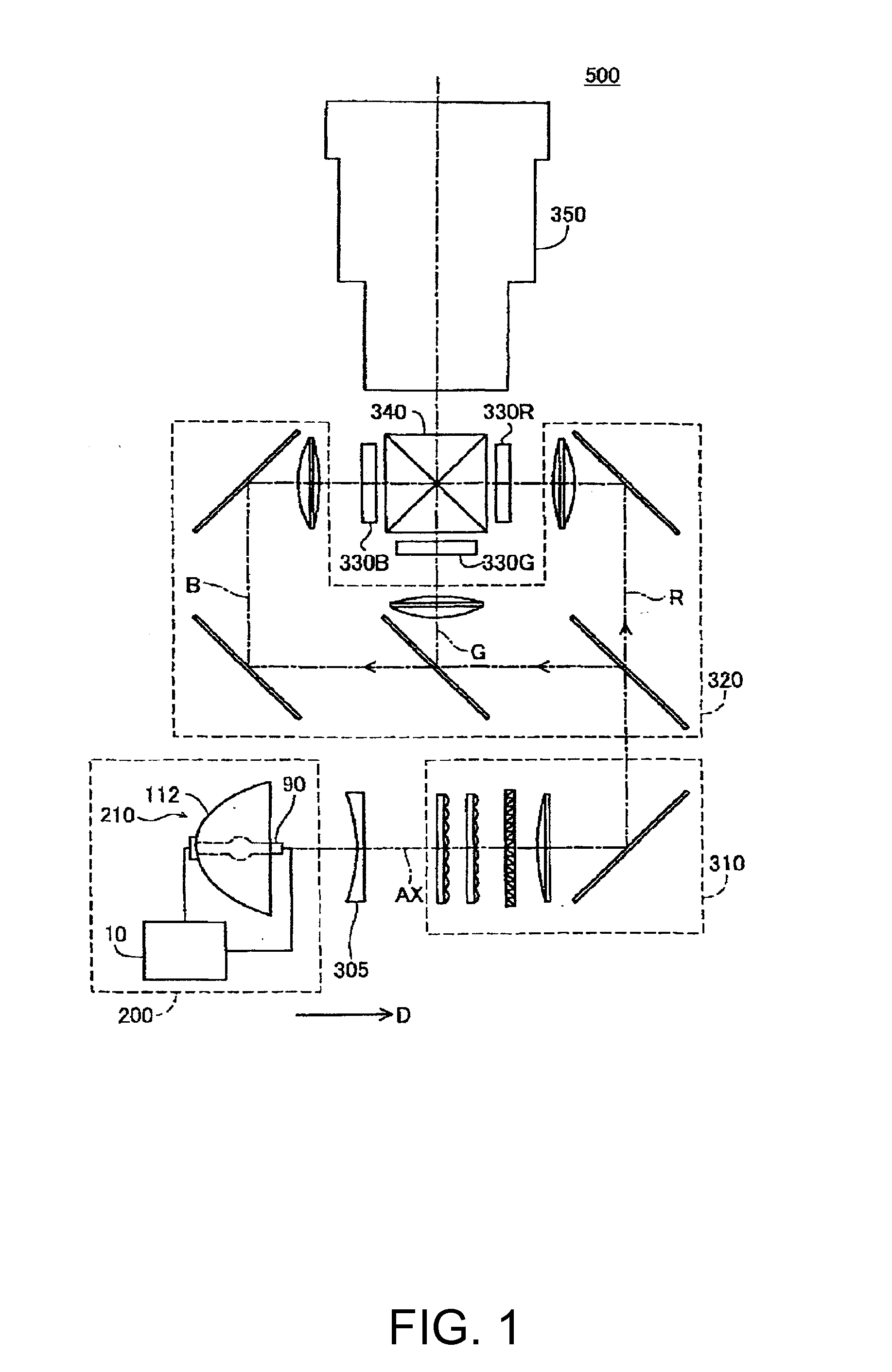
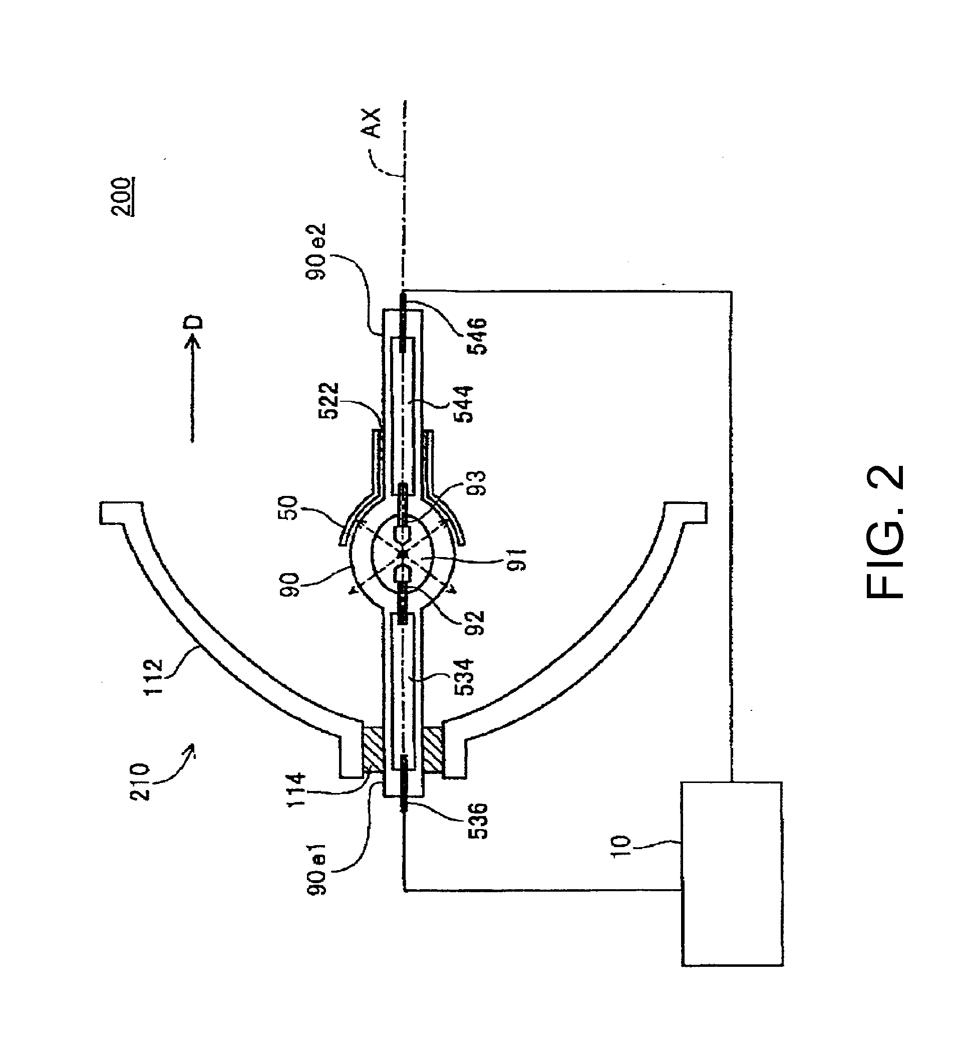
[0042]As illustrated in FIG. 1, a projector 500 of the present embodiment includes a light source device 200, a collimating lens 305, an illumination optical system 310, a color separation optical system 320, three liquid crystal light valves (light modulation elements) 330R, 330G, and 330B, a cross dichroic prism 340, and a projection optical system 350.

[0043]Light emitted from the light source device 200 passes through the collimating lens 305 and is incident on the illuminat...


PUM


Abstract

A discharge lamp driving device includes: a discharge lamp driving unit that supplies a driving current to the discharge lamp; and a control unit that controls the discharge lamp driving unit. The driving current having driving periods is supplied, the driving period including: a mixing period which alternately has an AC period in which an alternating current is supplied and a first DC period in which a direct current is supplied, a second DC period which is provided immediately after the mixing period and in which a direct current having a polarity which is the same as that of the direct current in the first DC period is supplied, and a third DC period which is provided immediately after the second DC period and in which a direct current having a polarity opposite to that of the direct current in the second DC period is supplied.

Description

BACKGROUND[0001]1. Technical Field[0002]The present invention relates to a discharge lamp driving device, a light source device, a projector, and a discharge lamp driving method.[0003]2. Related Art[0004]It is known that melting and solidifying of an electrode is repeated by making the temperature of an electrode of a discharge lamp fluctuate, and growth of a projection, which is a starting point of discharge, formed on a tip of the electrode can be controlled.[0005]As a method of controlling the growth of such a projection, a method of driving a discharge lamp alternately supplying the direct current and the alternating current to a discharge lamp has been proposed (For example, JP-A-2011-23154).[0006]The growth of a projection on the tip of the electrode becomes easily controlled as the fluctuation in temperature of the electrode is made to be large. However, in the driving method described above, the growth of a projection on the tip of the electrode is unlikely to be appropriate...

Claims


Application Information

Patent Timeline
IPC IPC(8): H05B41/392H04N9/31G03B21/00
CPCH05B41/3927H04N9/312G03B21/005H05B41/2883H05B41/3928H04N9/3105H04N9/3155G03B21/202
Inventor SUZUKI, JUNICHINAKAGOMI, YOICHI
Owner SEIKO EPSON CORP
Learn More