Microdevices and biosensor cartridges for biological or chemical analysis and systems and methods for the same

a biosensor and micro-device technology, applied in the field of biological or chemical analysis, can solve the problems of difficult to distinguish the true light signal from the well of interest from other unwanted light signals in the subsequent analysis, the above-pyrosequencing system, in addition to other systems, may have certain limitations, etc., to achieve the effect of increasing the control and efficiency of reactions and reducing costs

Active Publication Date: 2015-09-24
ILLUMINA INC
View PDF4 Cites 24 Cited by
  • Summary
  • Abstract
  • Description
  • Claims
  • Application Information

AI Technical Summary

Problems solved by technology

However, the above pyrosequencing system, in addition to other systems, may have certain limitations.
Although the wells may be approximately spaced apart from each other, it is difficult to know a precise location of a well in relation to other adjacent wells.
Inter-well crosstalk between the adjacent wells makes distinguishing true light signals from the well of interest from other unwanted light signals difficult in the subsequent analysis.
However, the high-resolution camera generates large amounts of data that must be analyzed that, in turn, may slow down the process.
The high-resolution camera can also be expensive.
However, these enzymatic strategies may increase the total costs of sequencing and may also negatively affect the system's ability to discern the true light signals for a certain well.
Some challenges that arise in delivering / removing the reagents and enzymes include bubble formation within a fluidic system.
Bubbles disrupt the flow of the fluids through the faceplate as well as negatively affect the imaging of a reaction sites.
Furthermore, if a system does not have uniform flow through the faceplate, then some wells may not be properly washed or may receive the reagents at different times or in different concentrations with respect to other wells in the chip.
This may lead to misleading or incorrect data.
However, the features and predetermined configuration of the CCD camera may not be suitable for other types of sequencing protocols or other assay protocols.
As such, the system may be limited to only those protocols that require the CCD camera to be predisposed in a similar way.

Method used


Image

  • Microdevices and biosensor cartridges for biological or chemical analysis and systems and methods for the same
  • Microdevices and biosensor cartridges for biological or chemical analysis and systems and methods for the same
  • Microdevices and biosensor cartridges for biological or chemical analysis and systems and methods for the same

Examples


Embodiment Construction

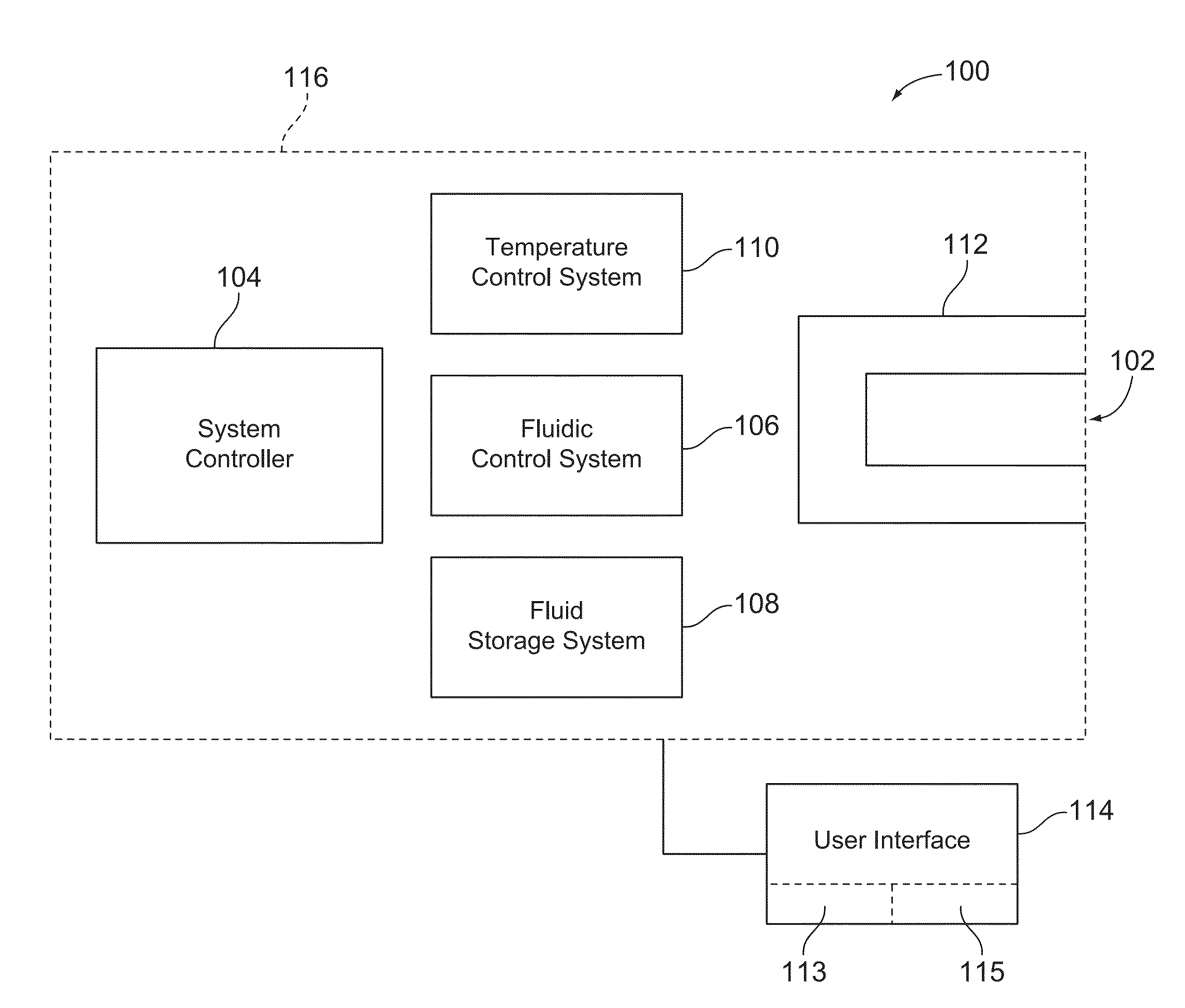
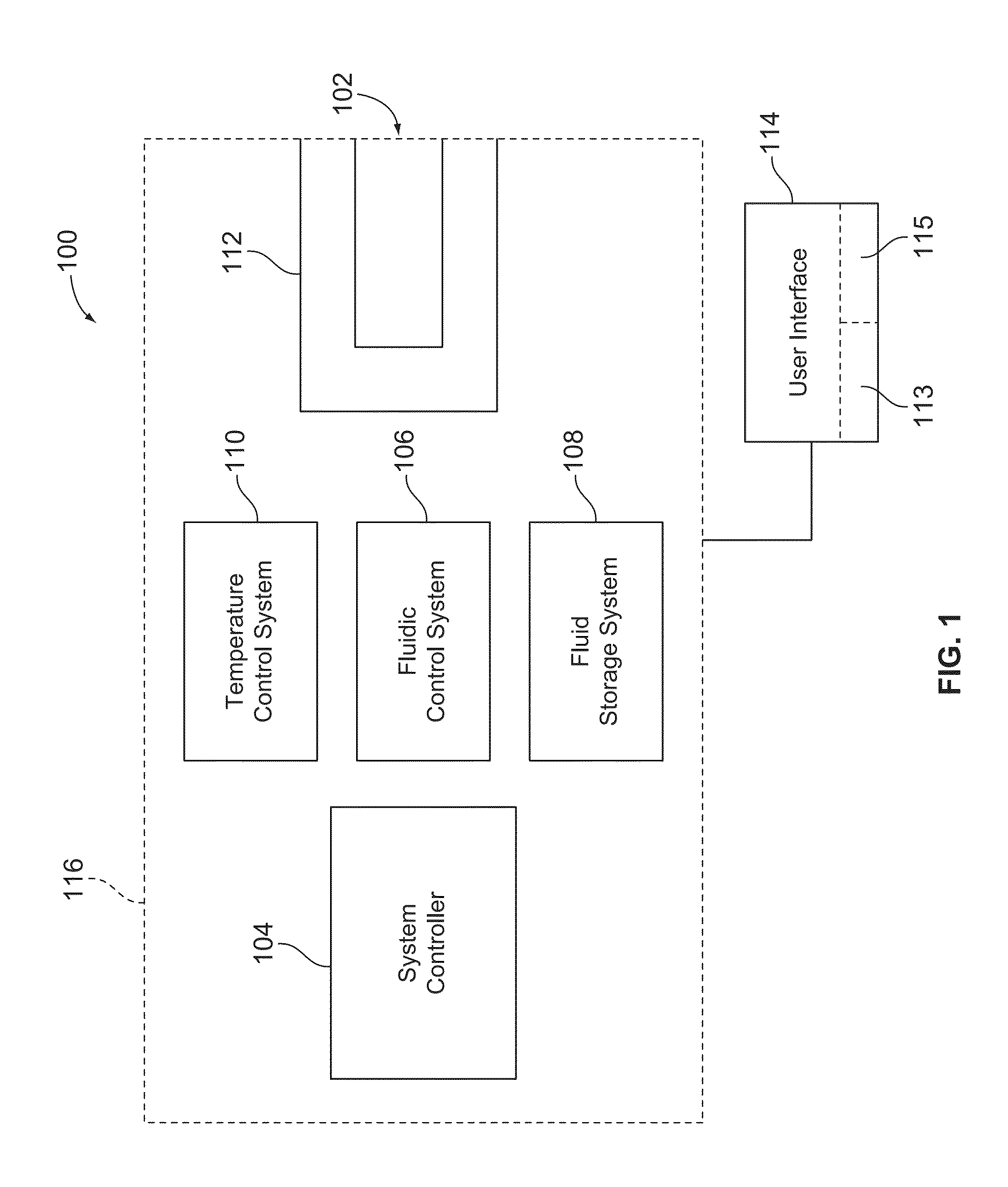
[0053]Embodiments described herein may be used in various biological or chemical processes and systems for academic or commercial analysis. More specifically, embodiments described herein may be used in various processes and systems where it is desired to detect an event, property, quality, or characteristic that is indicative of a desired reaction. For example, embodiments described herein include biosensor cartridges, microdevices, and their components as well as bioassay systems that operate with the biosensor cartridges and microdevices. In particular embodiments, the biosensor cartridges and microdevices include a flow cell and an activity detector that are coupled together in a substantially unitary structure.

[0054]The bioassay systems may be configured to perform a plurality of desired reactions that may be detected individually or collectively. The microdevices and bioassay systems may be configured to perform numerous cycles where the plurality of desired reactions occur in...


PUM

PropertyMeasurementUnit
contact angleaaaaaaaaaa
gravitational forceaaaaaaaaaa
dimensionsaaaaaaaaaa

Abstract

A flow cell including inlet and outlet ports in fluid communication with each other through a flow channel that extends therebetween. The flow channel includes a diffuser region and a field region that is located downstream from the diffuser region. The field region of the flow channel directs fluid along reaction sites where desired reactions occur. The fluid flows through the diffuser region in a first flow direction and through the field region in a second flow direction. The first and second flow directions being substantially perpendicular.

Description

CROSS REFERENCE TO RELATED APPLICATION[0001]The present application is a continuation of U.S. application Ser. No. 13 / 882,088 (“the '088 application”), filed Apr. 26, 2013, which is a National Stage of International Application No. PCT / US2011 / 057111, filed Oct. 20, 2011, which claims the benefit of U.S. Provisional Application Ser. No. 61 / 407,350 (“the '350 application”), filed Oct. 27, 2010. Each of the '088 application and the '350 application is incorporated herein by reference in its entirety.STATEMENT REGARDING FEDERALLY SPONSORED RESEARCH OR DEVELOPMENT[0002]This invention was made with Government support under NIH Grant Number HG003571 awarded by the PHS. The Government has certain rights in the invention.BACKGROUND OF THE INVENTION[0003]Embodiments of the present invention relate generally to biological or chemical analysis and more particularly, to systems and methods using microfluidic and detection devices for biological or chemical analysis.[0004]Various protocols in bio...

Claims


Application Information

Patent Timeline
Patent Type & Authority Applications(United States)
IPC IPC(8): B01L3/00C12Q1/68
CPCB01L3/502715C12Q1/6874B01L2300/0877B01L2300/0645B01L2300/0819B01L2300/022B01L2200/10C12Q1/6869B01L3/5085B01L7/52B01L2200/025B01L2200/04B01L2300/048B01L2300/0636B01L2300/0654B01L2300/161B01L2400/0457B01L2200/082B01L2200/16B01L2300/023B01L2300/0627B01L2300/165B01L2400/0487B01L2400/0622
Inventor ELTOUKHY, HELMY A.KHURANA, TARUNJAVANMARDI, BEHNAMSABOUNCHI, POORYAAGHABABAZADEH, MAJID
Owner ILLUMINA INC
Why Eureka
Try Eureka