
Drill pipe screens and related methods

a technology of drill pipe and pipe screen, which is applied in the direction of drinking water installation, earthwork drilling tools, borehole/well accessories, etc., can solve the problems of difficult extrapolation, high sensitive turbines within such alternators, and limited vertical wells

Active Publication Date: 2015-09-24
PATTERSON JAMES
View PDF9 Cites 8 Cited by
  • Summary
  • Abstract
  • Description
  • Claims
  • Application Information

AI Technical Summary

Benefits of technology

The present invention provides drill pipe screens and methods that can effectively filter drilling mud without causing intermittent pressure spikes or allowing debris to pass through. The screens are designed with alternating patterns of elongated parallel slots and small peripheral relief ports, which provide strong peripheral strength to the tubes and prevent breakage. The invention also ensures that wide peripheral integrity bands with sufficient length are provided in the tubes between sets of slots and relief ports to avoid breakage, while the presence of the relief ports prevents the occurrence of pressure spikes when the screens are not completely clogged. The screens are durable and resist breakage, preventing debris from passing through.

Problems solved by technology

Conventional vertical wells are limited by surface land formations limiting possible rig set up, and subterranean oil formations that are extremely difficult to extrapolate through conventional methods for maximum oil production.
It is well known that the turbines within such alternators are highly sensitive.
If a turbine is damaged, a power failure may occur resulting in loss of electricity to the directional sensors.
This can bring horizontal drilling operations to a halt until the turbines are repaired or replaced, which can be a very expensive and time consuming process since it requires removal of the entire drill string from the well, repair / replacement of the turbine alternators, and reinsertion of the drill string into the well.
It is to be appreciated that when such a screen or filter becomes clogged, there is usually an associated spike in the pressure of the drilling mud used to operate the turbines.
When such a spike is noticed, it is a signal to the drilling operators to change the screen, or risk damage to the drill string from buildup of excessive pressure.
Replacing the drill pipe screen is a cumbersome process, requiring drilling operations to be shut down while the filter is removed, cleaned and / or replaced, but this preferable to a blowout from excessive pressure, or causing damage to the turbines at the other end of the drill string.
However, each of these types of drill pipe screen suffers from one or more disadvantages.
For example and without limitation, existing drill pipe screens (particularly spiral and slotted tube screens) tend to clog readily, and may cause a spike in drilling mud pressure after a relatively short period of time (e.g., 2-3 runs).
In addition, existing drill pipe screens may cause small pressure spikes even though the screen may not be completely clogged, forcing the drilling operators to stop operations to check the status of the screen only to find that it is not significantly clogged and operations could have continued.
This results in unnecessary downtime to check and thereafter clean or replace a drill pipe screen that did not actually need to be serviced.
Current screens also suffer extensive failures due to damage sustained to the base metal of the screen (particularly bar-rod and perforated screens) allowing debris to pass through the screen and reach the sensitive turbine, potentially causing serious damage and drilling down time, and loss of drilling mud circulation which affects all drilling processes.
However, as vital as drill pipe screens are to horizontal drilling, screen designs have not changed in the industry for an extended length of time.

Method used


Image

  • Drill pipe screens and related methods
  • Drill pipe screens and related methods
  • Drill pipe screens and related methods

Examples


Embodiment Construction

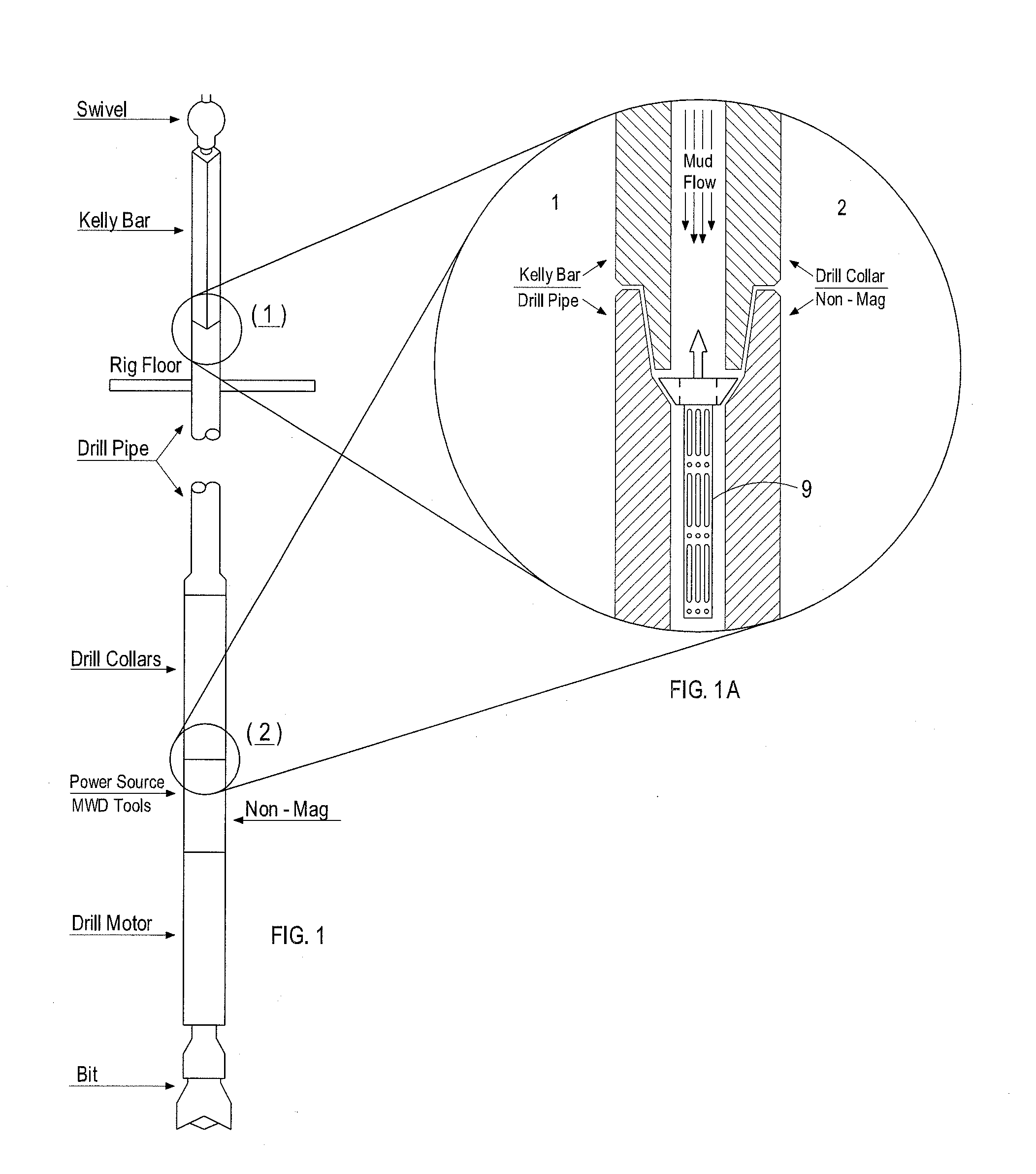
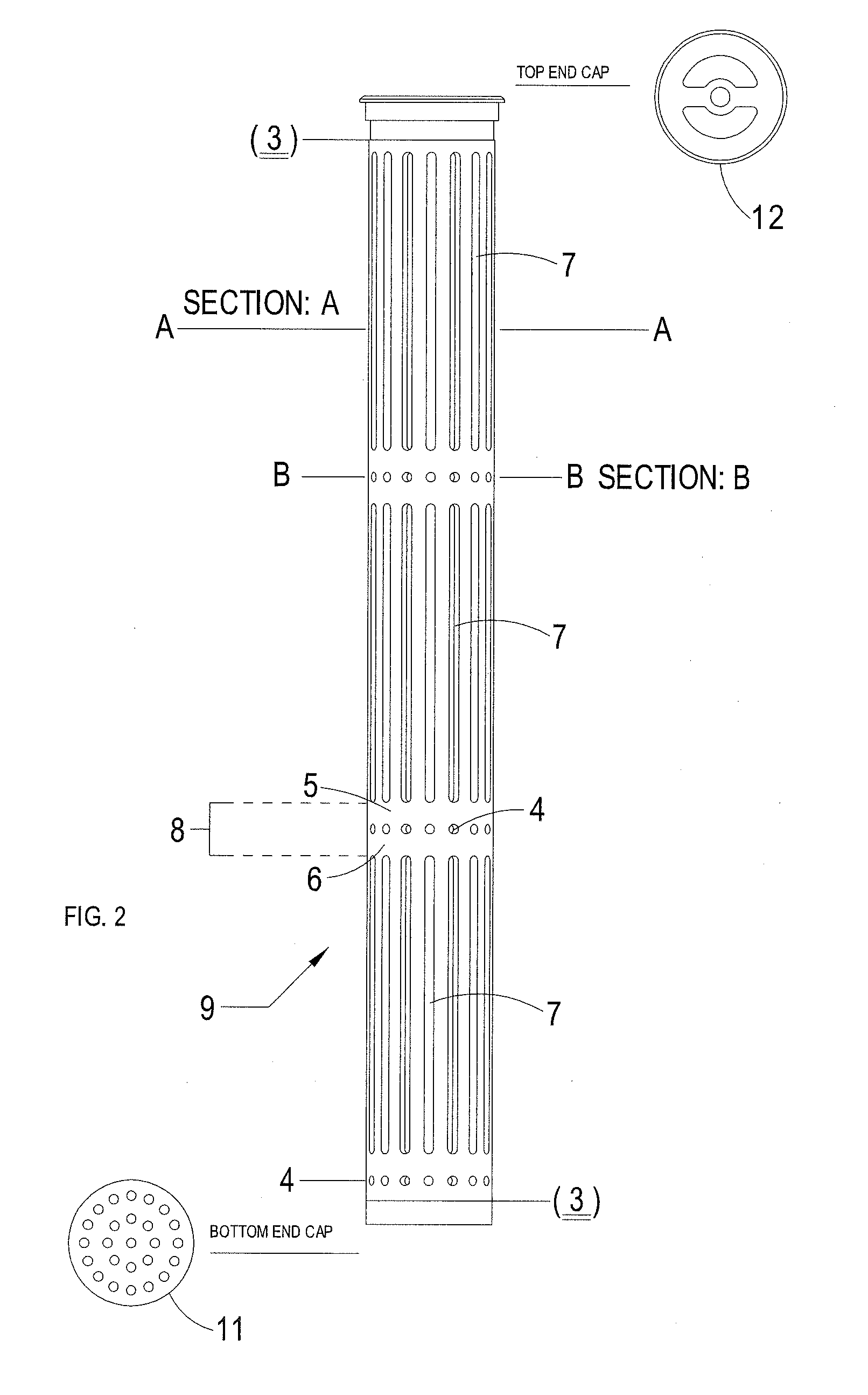
[0030]Referring to the drawings wherein like reference characters designate like or corresponding parts throughout the several views, and referring particularly to FIG. 5, it is seen that this illustrated embodiment of the present invention includes an elongated cylindrical body 9 to which a lower end cap 11 and an upper end cap 12 are to be attached. Referring to FIG. 2, it is seen that the illustrated cylindrical body 9 includes at least one set of elongated slots 7 separated longitudinally along the length of cylindrical body 9 by at least one set of relief ports 4. The slots 7 of each set are provided in parallel to each other, and parallel to the central axis of the cylindrical body 9. The relief ports 4 of each set are provided longitudinally between each set of slots 7. In the illustrated embodiment, a set of relief ports is also provided at the bottom end of cylindrical body 9. Although the illustrated embodiments show three sets of slots 7 and three sets of ports 4, it is t...


PUM


Abstract

The present invention includes drill pipe screens and related methods that provide reliable long-term filtering of drilling fluids used to operate alternator turbines that are used to provide power in measurement while drilling (MWD) systems without allowing debris to pass through the screens to the turbines, and without causing intermittent pressure spikes at times when the screens are not completely clogged while maintaining desired circulation rates of drilling fluids. Embodiments of the invention include cylindrical bodies having alternating sets of elongated slots and peripheral ports located thereon to provide filtering of and relief to drilling fluids under pressure.

Description

BACKGROUND OF THE INVENTION[0001]1. Field of Invention[0002]The present invention relates to equipment utilized during measurement while drilling (MWD) data retrieval in subterranean wells. In particular, the invention relates to filtering apparatus and related methods for preventing debris from entering sensitive areas in a drilling system such as a turbine power source used to operate directional sensors, while maintaining desired flow rates for optimal drilling.[0003]2. Description of the Related Art[0004]Horizontal (directional) drilling continues to prove to be an extremely efficient method for retrieving oil. Conventional vertical wells are limited by surface land formations limiting possible rig set up, and subterranean oil formations that are extremely difficult to extrapolate through conventional methods for maximum oil production. Horizontal drilling offers a solution to many complications currently faced through conventional vertical wells. Some of the most important piec...

Claims


Application Information

Patent Timeline
IPC IPC(8): E21B43/08E21B43/10
CPCE21B43/10E21B43/086E21B12/00E21B21/002E21B27/005
Inventor PATTERSON, JAMES
Owner PATTERSON JAMES
Learn More