
Turbine nozzles with slip joints impregnated by oxidation-resistant sealing material and methods for the production thereof

Active Publication Date: 2015-09-24
HONEYWELL INT INC
View PDF9 Cites 7 Cited by
  • Summary
  • Abstract
  • Description
  • Claims
  • Application Information

AI Technical Summary

Benefits of technology

This patent relates to a turbine nozzle with slip joints that are impregnated with a special material resistant to oxidation. The special material, called silicon-modified aluminide, helps prevent gas from leaking into the joints during operation of the turbine. It also allows for relative movement between the turbine nozzle parts during operation. This results in improved performance and durability of the turbine nozzle.

Problems solved by technology

Turbine nozzles of this type (referred to herein as “segmented turbine nozzles”) may, however, be prone to gas flow leakage across the mating interfaces between adjoining segments and flange surfaces.
Gas flow leakage may increase chargeable cooling flow to the cycle, reduce cooling flow from the combustor, and result in a direct penalty against overall gas turbine engine performance.
While providing the above-noted advantages, bi-cast turbine nozzles remain limited in certain respects.
Hot gas ingestion may cause oxidative damage to the slip joint surfaces and detract from the aerodynamic performance of the turbine nozzle.
Over the lifespan of the turbine nozzle, oxidation and hot corrosion may further erode the uncoated surfaces of the slip joints resulting in increasingly large air gaps and still further reductions in the aerodynamic performance of the turbine nozzle.

Method used


Image

  • Turbine nozzles with slip joints impregnated by oxidation-resistant sealing material and methods for the production thereof
  • Turbine nozzles with slip joints impregnated by oxidation-resistant sealing material and methods for the production thereof
  • Turbine nozzles with slip joints impregnated by oxidation-resistant sealing material and methods for the production thereof

Examples


Embodiment Construction

[0014]The following Detailed Description is merely exemplary in nature and is not intended to limit the invention or the application and uses of the invention. Furthermore, there is no intention to be bound by any theory presented in the preceding Background or the following Detailed Description. Terms such as “comprise,”“include,”“have,” and variations thereof are utilized herein to denote non-exclusive inclusions. Such terms may thus be utilized in describing processes, articles, apparatuses, and the like that include one or more named steps or elements, but may further include additional unnamed steps or elements. The term “radial slip joint,” the term “slip joint,” and similar terms and phrases are utilized to denote an interface created between two closely positioned surfaces allowing relative radial movement therebetween. The closely positioned surfaces may be separated by an air gap or, instead, intervening structural elements and / or materials (e.g., sealing materials of the ...


PUM

PropertyMeasurementUnit
Percent by massaaaaaaaaaa
Weightaaaaaaaaaa

Abstract

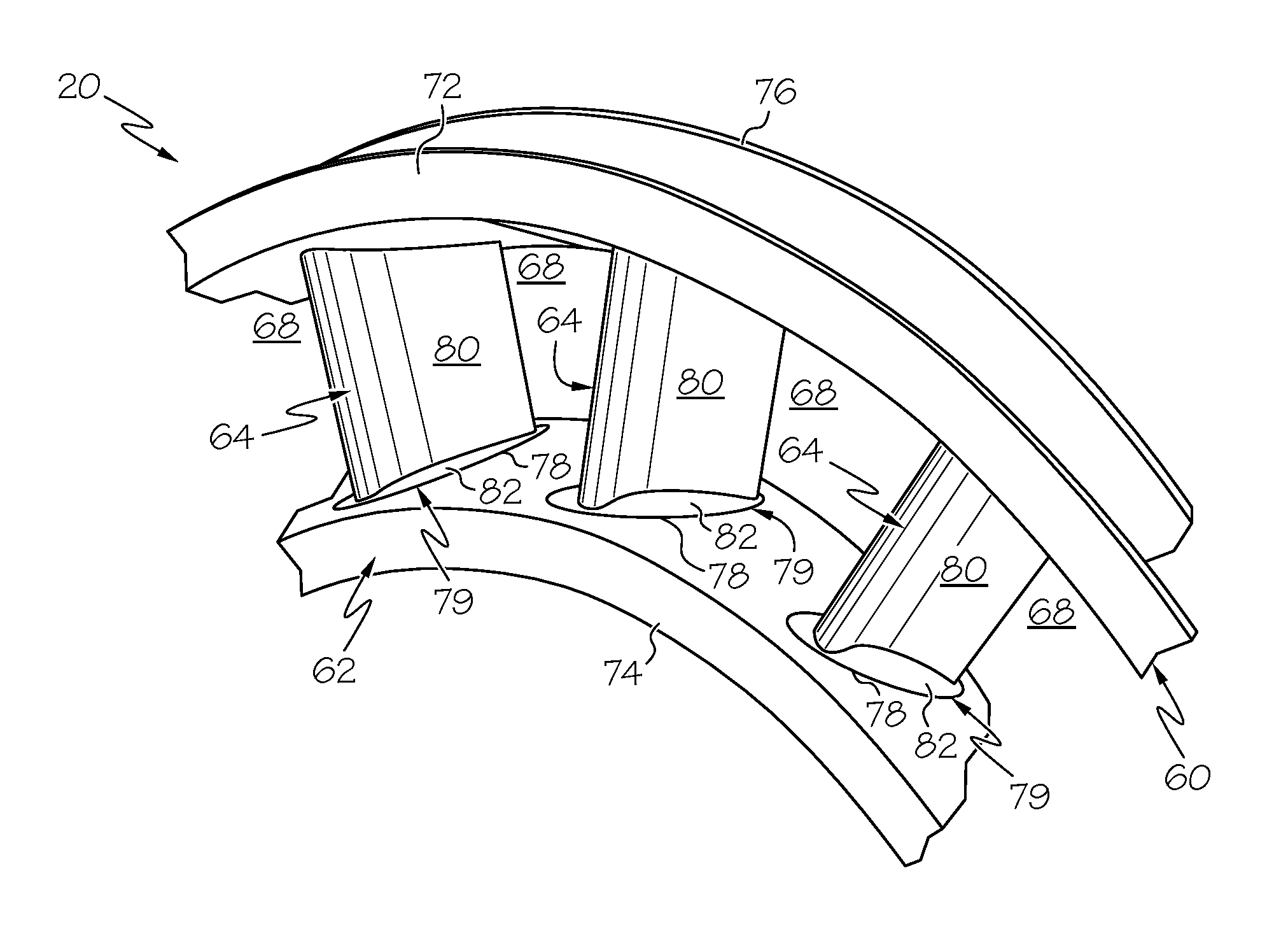
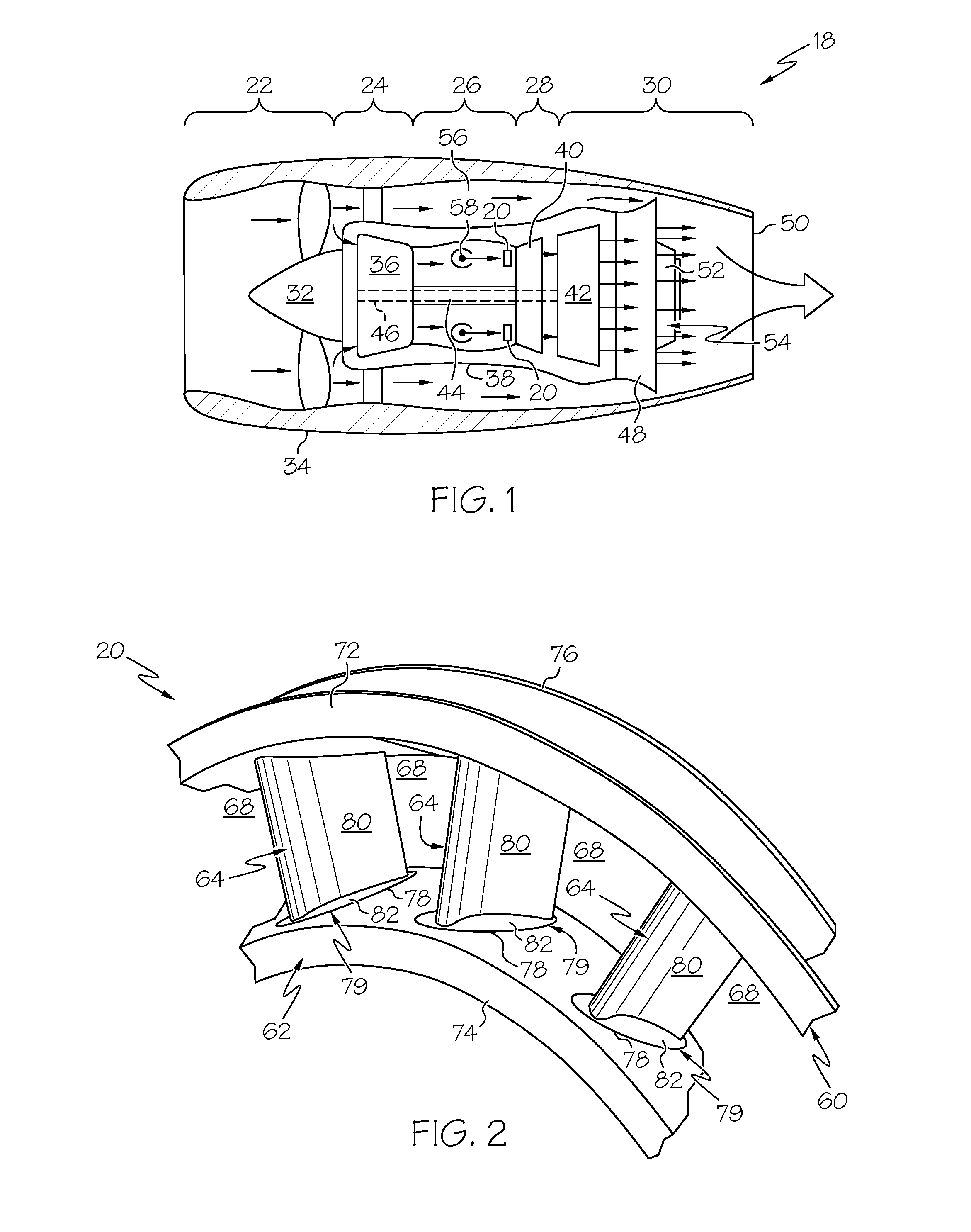
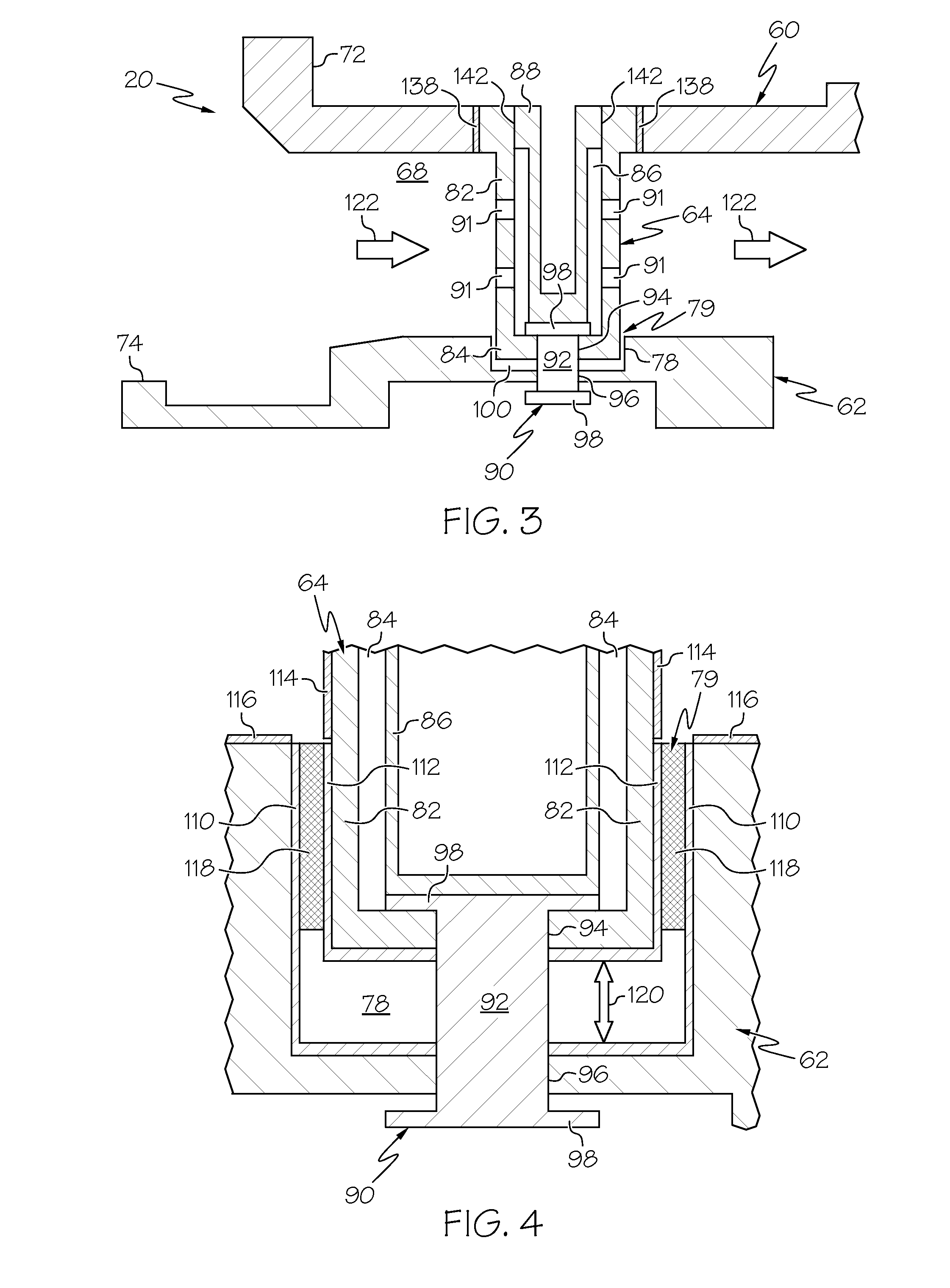
Embodiments of a turbine nozzle having slip joints impregnated by an oxidation-resistant sealing material are provided, as are embodiments of methods for the manufacture of turbine nozzles. In one embodiment, the method includes providing a support ring, a slip joint ring substantially concentric with the support ring and radially spaced apart therefrom, and a plurality of vanes fixedly coupled to the support ring. The plurality of vanes extends radially from the support ring into a plurality of circumferentially-spaced slots provided in the slip joint ring to form a plurality of slip joints therewith. The plurality of slip joints are impregnated with a silicon-modified aluminide sealing material. The silicon-modified aluminide sealing material impedes gas flow into the radial slip joints during operation of the turbine nozzle, while also fracturing to permit relative radial movement between the plurality of vanes and the slip joint ring along the plurality of slip joints.

Description

STATEMENT REGARDING FEDERALLY-SPONSORED RESEARCH OR DEVELOPMENT[0001]This invention was made with Government support under W911W6-08-2-0001 awarded the U.S. Army. The Government has certain rights in the invention.TECHNICAL FIELD[0002]The following disclosure relates generally to gas turbine engines and, more particularly, to turbine nozzles and methods for producing turbine nozzles having slip joints impregnated with an oxidation-resistant sealing material, such as a silicon-modified aluminide sealing material.BACKGROUND[0003]Gas turbine engine are often produced to include turbine nozzles, which meter combustive gas flow, while also accelerating and turning the gas flow toward the blades of a turbine rotor positioned downstream of the nozzle. A turbine nozzle may be assembled from a number of separately-produced segments, which each include an arced segment of the inner endwall or ring, an arced segment of the outer endwall or ring, and one or more airfoils or vanes extending ther...

Claims


Application Information

Patent Timeline
IPC IPC(8): F01D11/00B23K1/00B23P15/04
CPCF01D11/005B23K2201/001B23K1/0018B23P15/04F01D5/28F01D9/041F01D9/042F01D11/00F01D17/162F05D2300/182Y10T29/49321B23K2101/001Y02T50/60
Inventor KANJIYANI, SHEZANTUCKER, BRADLEY REEDWALI, NATALIEHICKS, DANIELMACELROY, BILL
Owner HONEYWELL INT INC
Learn More