Physical quantity sensor, method for manufacturing physical quantity sensor, pressure sensor, altimeter, electronic device, and moving object

Inactive Publication Date: 2015-09-24
SEIKO EPSON CORP
View PDF33 Cites 8 Cited by
  • Summary
  • Abstract
  • Description
  • Claims
  • Application Information

AI Technical Summary

Benefits of technology

[0032]Accordingly, there can be provided the moving object including the physical quantity sensor that can increase the

Problems solved by technology

When there is a positional dislocation during the bonding of the silicon wafer and the substrate, the accuracy of positioning the diaphragm and the strain sensing element may decrease, and

Method used


Image

  • Physical quantity sensor, method for manufacturing physical quantity sensor, pressure sensor, altimeter, electronic device, and moving object
  • Physical quantity sensor, method for manufacturing physical quantity sensor, pressure sensor, altimeter, electronic device, and moving object
  • Physical quantity sensor, method for manufacturing physical quantity sensor, pressure sensor, altimeter, electronic device, and moving object

Examples


first embodiment

1. Physical Quantity Sensor

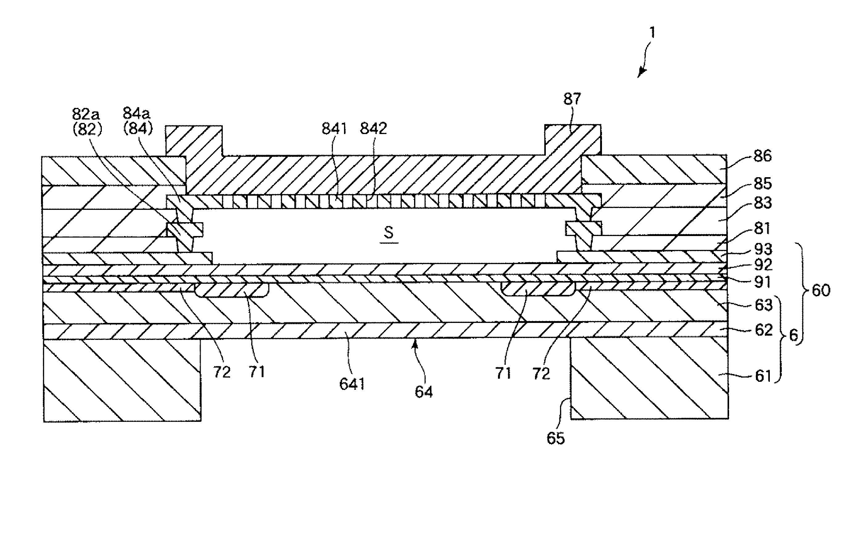
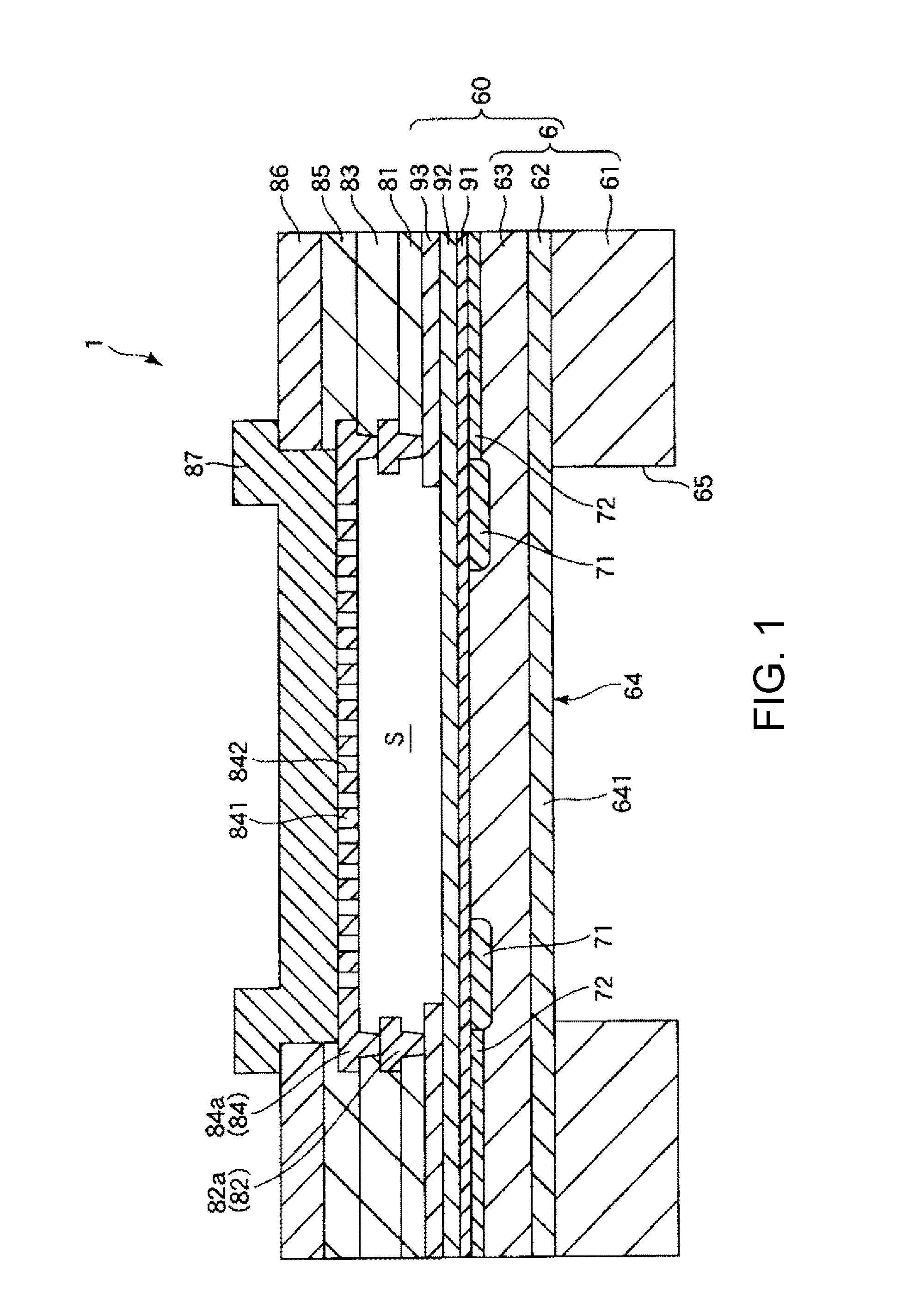
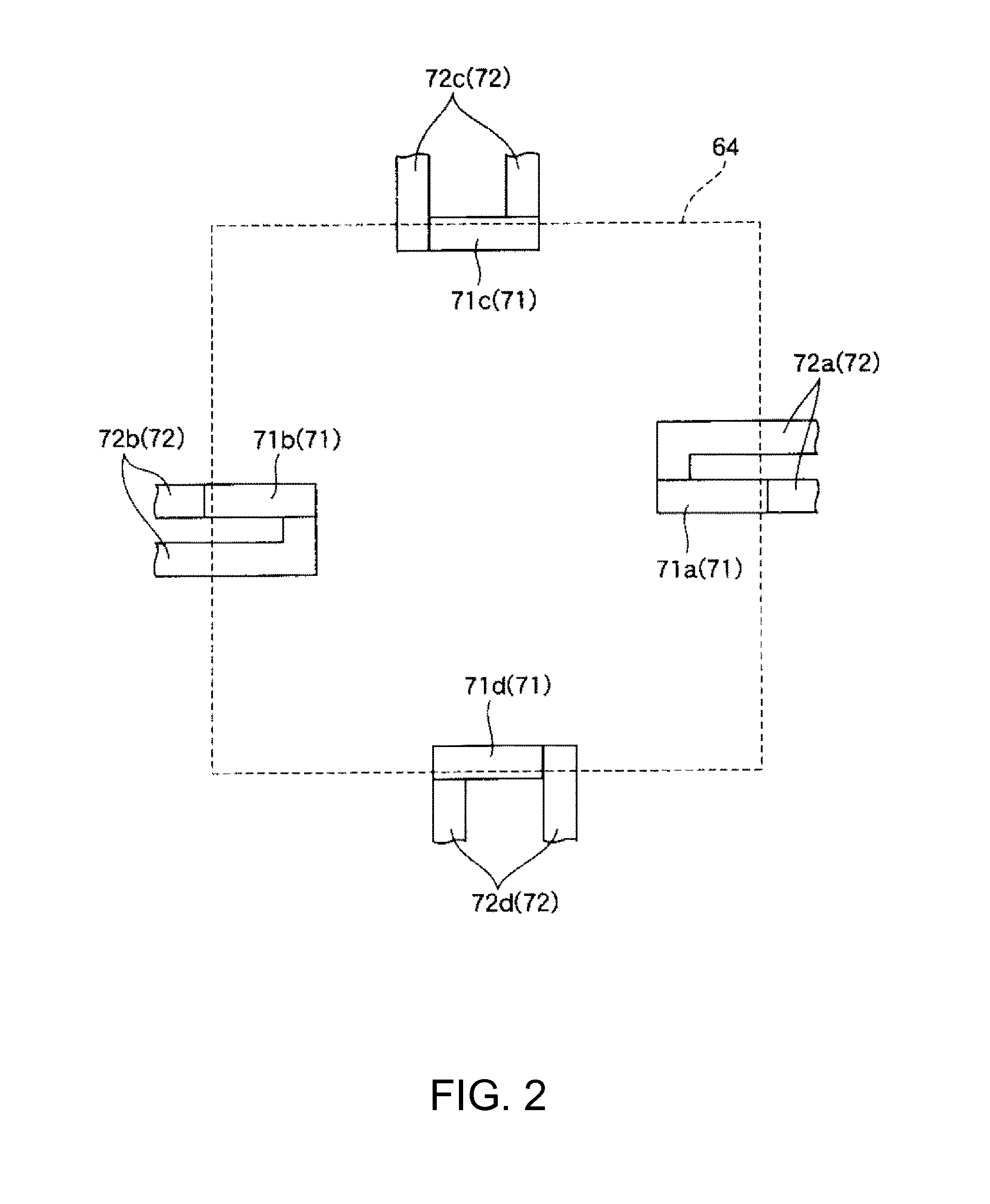
[0045]FIG. 1 is a cross-sectional view illustrating a physical quantity sensor according to an embodiment of the invention. FIG. 2 is a plan view illustrating the enlarged arrangement of a piezoresistive element of the physical quantity sensor illustrated in FIG. 1. FIGS. 3A and 3B are diagrams for describing the operation of the physical quantity sensor illustrated in FIG. 1. FIG. 3A is a cross-sectional view illustrating a pressurization state, and FIG. 3B is a plan view illustrating a pressurization state. An upper side in FIG. 1 is referred to as “on” and a lower side as “under” hereinafter for convenience of description.

[0046]A physical quantity sensor 1 illustrated in FIG. 1 is provided with a substrate 6 and a laminated structure 8. The laminated structure 8 is disposed on the upper surface of the substrate 6 with a silicon oxide film 91, a silicon nitride film 92, and a polysilicon film 93 interposed therebetween. A substrate 60 is a laminated body...


PUM


Abstract

A physical quantity sensor includes a substrate, a piezoresistive element, and a laminated structure. The substrate has a diaphragm portion deformed flexibly when receiving pressure. The piezoresistive element is arranged on one surface of the diaphragm portion. The laminated structure is arranged on the piezoresistive element side of the diaphragm portion and constitutes with the diaphragm portion a cavity portion that is a pressure reference chamber. The laminated structure is formed by using a CMOS process.

Description

BACKGROUND[0001]1. Technical Field[0002]The present invention relates to a physical quantity sensor, a method for manufacturing the physical quantity sensor, a pressure sensor, an altimeter, an electronic device, and a moving object.[0003]2. Related Art[0004]A pressure sensor is widely used that is provided with a diaphragm deformed flexibly when receiving pressure. Such a pressure sensor is known to detect the pressure exerted on the diaphragm in a manner in which a piezoresistive element is arranged on the diaphragm, and a sensor element detects the curvature of the diaphragm (for example, refer to JP-A-2001-332746).[0005]For example, the pressure sensor disclosed in JP-A-2001-332746 includes a silicon wafer and a substrate that are bonded together. A recess portion is formed on the surface of the substrate on the silicon wafer side in order to form a cavity portion (pressure reference chamber) between the silicon wafer and the substrate. Then, the silicon wafer is thinned so that...

Claims


Application Information

Patent Timeline
IPC IPC(8): G01L9/00
CPCG01L9/0054G01C5/06
Inventor TAKEUCHI, MASAHIRO
Owner SEIKO EPSON CORP
Why Eureka
Try Eureka