

Control device for in-vehicle solar cell
a control device and solar cell technology, applied in the direction of electric digital data processing, instruments, computing, etc., can solve the problem of not being able to efficiently extract electric energy
- Summary
- Abstract
- Description
- Claims
- Application Information
AI Technical Summary
Benefits of technology
Problems solved by technology
Method used
Image

Examples
first embodiment
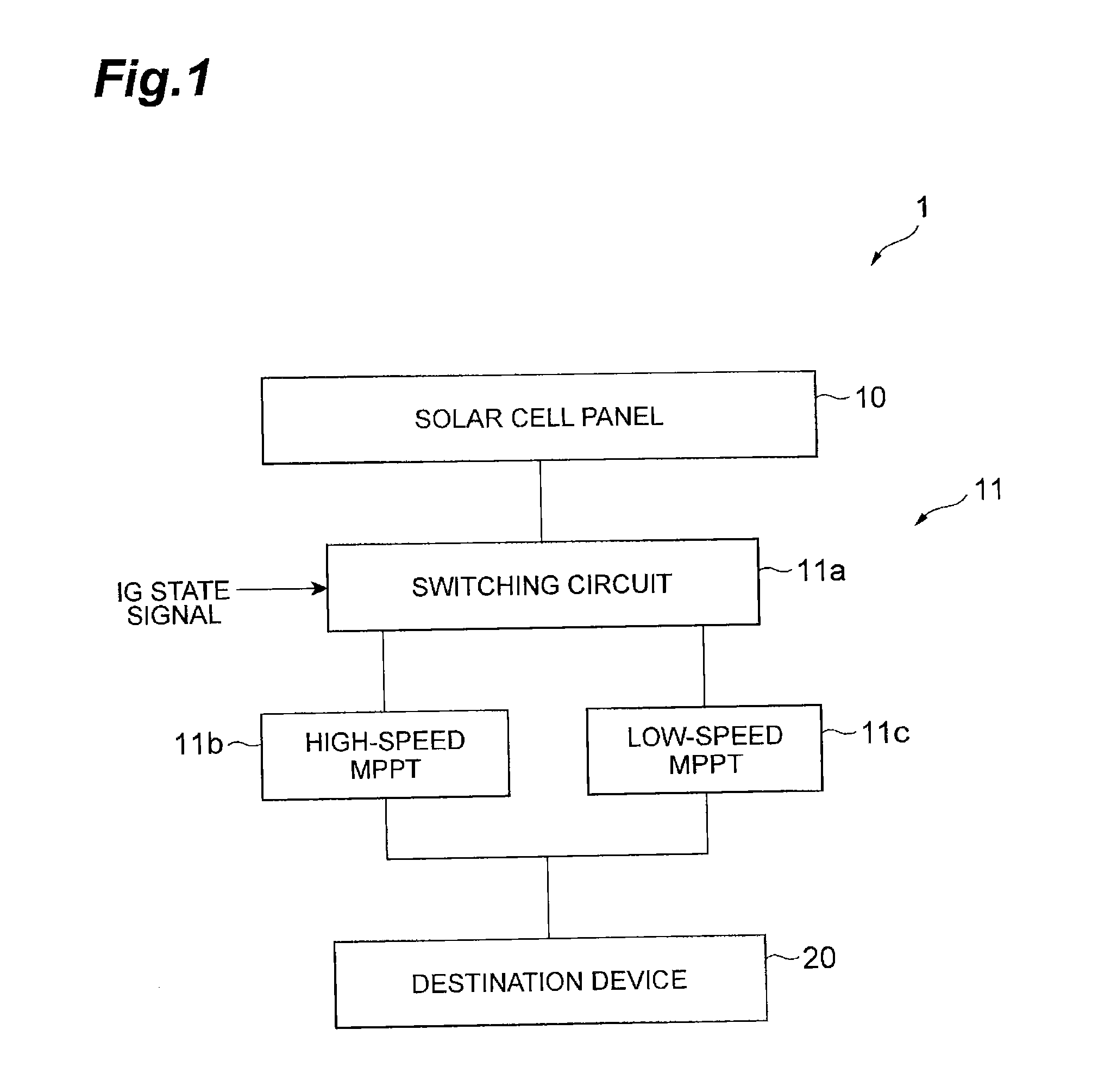
[0049]The control device 11 includes a switching circuit 11a, a high-speed MPPT 11b, and a low-speed MPPT 11c. The solar cell panel 10 and the destination device 20 are connected to the control device 11. In the first embodiment, the switching circuit 11a corresponds to a determination unit and a switching unit described in the claims, and the high-speed MPPT 11b and the low-speed MPPT 11c correspond to a plurality of MPPTs having different control cycles described in the claims.
[0050]The switching circuit 11a is an electric circuit for switching between the high-speed MPPT 11b and the low-speed MPPT 11c on the basis of the state of the IG switch. An ignition state signal indicating the state of the IG switch (not illustrated) (hereinafter, referred to as the IG state signal) is input to the switching circuit 11a, and the high-speed MPPT 11b and the low-speed MPPT 11c are connected to the switching circuit. In the switching circuit 11a, it is determined whether the IG state signal i...
second embodiment
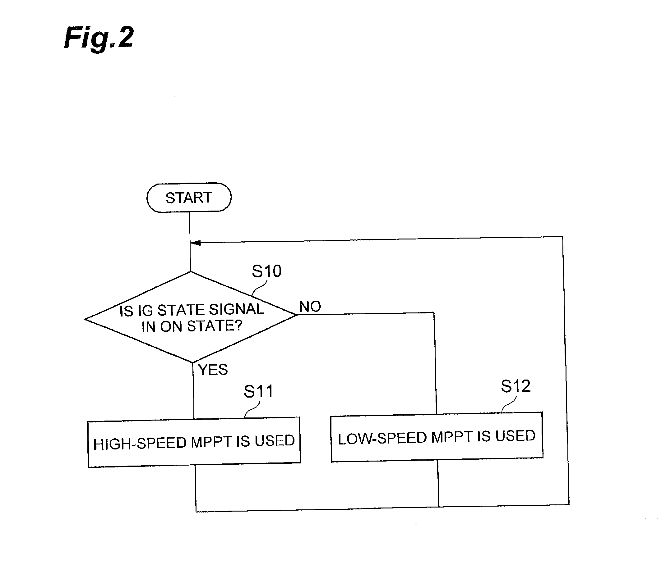
[0061]The operation of the solar cell system 2 having the above-described constitution will be described using the flowchart of FIG. 4. FIG. 4 is a control flowchart according to the
[0062]In the control cycle-variable MPPT 12a, it is determined whether or not the IG state signal is in the ON state (S20). In a case in which the IG state signal is determined to be in the ON state in S20 (in a case in which the vehicle is determined to be travelling), in the control cycle-variable MPPT 12a, the control cycle is set to be short in order to speed up the control cycle of the MPPT control circuit (S21). In the MPPT control circuit of the control cycle-variable MPPT 12a, the optimal operation points of the solar cell panel 10 in accordance with the current insolation conditions are obtained with short control cycles, and feedback control is performed on the solar cell panel 10 so that the optimal operation points are obtained. On the other hand, in a case in which the IG state signal is det...
third embodiment
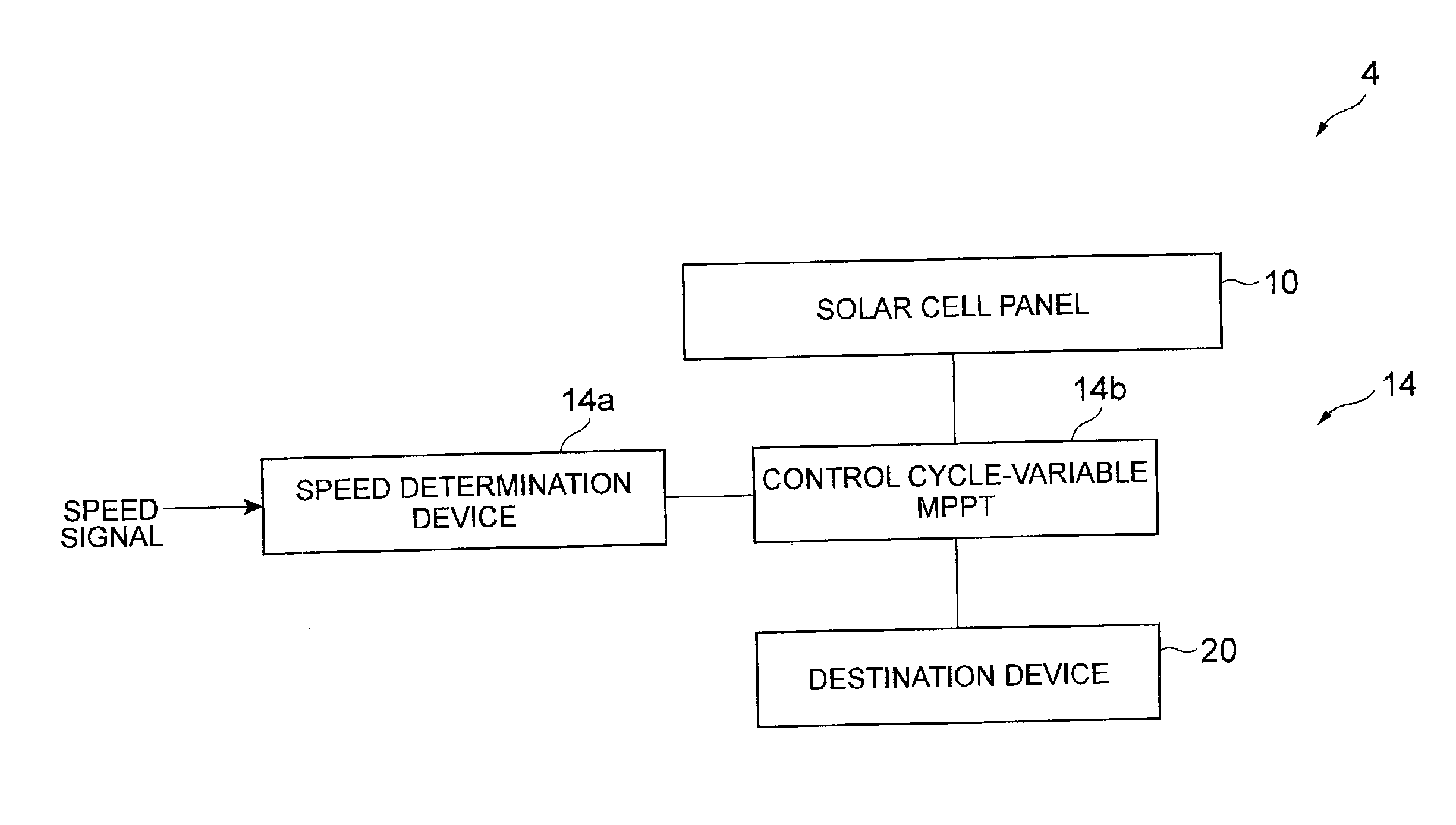
[0070]The operation of the solar cell system 3 having the above-described constitution will be described using the flowchart of FIG. 6. FIG. 6 is a control flowchart according to the
[0071]In the speed determination device 13a, it is determined whether or not the speed indicated using the speed signal is equal to or more than 10 km / h (S30). In a case in which the speed is equal to or more than 10 km / h in S30, in the speed determination device 13a, the vehicle is determined to be travelling, and a determination result signal indicating the vehicle travelling is output to the switching circuit 13b. In the switching circuit 13b, on the basis of the determination result signal indicating the vehicle travelling, the high-speed MPPT 13c is operated in order to use the high-speed MPPT 13c (S31). In the high-speed MPPT 13c, the same operation as the operation of the high-speed MPPT 11b according to the first embodiment is performed. On the other hand, in a case in which the speed is less tha...
PUM
 Abstract
Description
Claims
Application Information